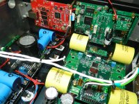
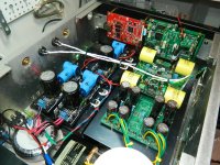
OK thank hochopeper ,I wanted to use 3 AFL Coaxial cable,but I need to use the 7 pin connector input.
No worries 🙂 Just to elaborate, 7pin cable is just fine before the FIFO. Be sure to connect a ground wire adjacent each signal wire in the cable to have gsgsgsg (g=gnd, s=signal) There may be some minor reduction in radiated noise by having u.fl carry the input. If the source doesn't have u.fl then its probably just as good to use the 7pin ph cable.
Last edited:
hi guys.
i have my unit setup with spdif board, fifo, dual clock, and isolator board. i have separate 6v battery for each fifo and clock.
am i on the safe side with the battery voltages?
thanks guys
i have my unit setup with spdif board, fifo, dual clock, and isolator board. i have separate 6v battery for each fifo and clock.
am i on the safe side with the battery voltages?
thanks guys
impossible to tell, depends on the battery, some 6v could easily be under 5v when low on charge. battery voltages are never constant.
Another issue that I work, with the DSP of the Ref 7.1ºÍ§Ó*µ响 , what are the optimal frequencies of clocks that I have to put on the FIFO card clocks?
I would have like to have an answer please
why dont you ask the dac designer? it seems a question that should be aimed at him, not Ian or this thread. he uses some sort of custom digital filter for the 1704 if I remember correctly, so its not really our place to do the research.
Yes QUSP you're right; after the response I said here, it can be used to someone.I ask here because there are a lot of resources 🙂
cool, do, some may be interested. without knowing the details of the digital filter its difficult to make a recommendation and since its custom, made with a DSP of some sort I think, the only one with all the details will be the designer, as there is no datasheet.
The Si570 guide that Ian wrote has the instructions 🙂
The *Fs will change depending on the input data rate. See the group definitions for what to expect. If you have 512Fs you will have 176.x and 192kHz ...
To program group4 as the default combination, manually set the frequency to 98.3040MHz or 90.3168MHz
The *Fs will change depending on the input data rate. See the group definitions for what to expect. If you have 512Fs you will have 176.x and 192kHz ...
The Si570 guide that Ian wrote has the instructions 🙂
The *Fs will change depending on the input data rate. See the group definitions for what to expect. If you have 512Fs you will have 176.x and 192kHz ...
Thanks hochopeper 🙂
I need help 🙂 I understand how to select the frequency 98xxx and 90xxx XO570. But how do I select 2048Fs, 1024Fs, 512Fs, 256Fs? To me it is always lit LED 512Fs.
Thank you!
hochopeper gave perfect answer.
Yes, *Fs is decide by the selected MCLK and the the Fs of your music. *Fs is not a selectable setting.
For example, if you select 98.304Mhz as MCLK, and you are playing 96KHz music, so the *Fs is determined to be 98.304Mhz/96KHz =1024*Fs.
BTW, Your system looks great, but my D1 is still keeping unassembled 🙂
Ian
Thanks Ian, is very clear to me now 🙂
I have not removed the buffalo3 XO. I did as it is here:
Buffalo III external clock - Buffalo DAC - Twisted Pear Audio Support
I hope it will work 🙂
Expect to receive in stock A123 after that to see how it sounds.
I have not removed the buffalo3 XO. I did as it is here:
Buffalo III external clock - Buffalo DAC - Twisted Pear Audio Support
I hope it will work 🙂
Expect to receive in stock A123 after that to see how it sounds.
leaving it unpowered disables it, but that isnt what we need, we need it to be actively in shutdown afaik, otherwise its output stage will be in parallel with the new clock input. it works, but its not ideal and will effect the clock wave shape. unless TP have done something i'm not aware of.
leaving it unpowered disables it, but that isnt what we need, we need it to be actively in shutdown afaik, otherwise its output stage will be in parallel with the new clock input. it works, but its not ideal and will effect the clock wave shape. unless TP have done something i'm not aware of.
How remove XO?
What's best to do so without destroying XO?
Any experience is welcome to me.
Thank you 🙂
get one of the chipquik SMD removal kits, make sure to wick it all off nd clean the solderpads, so that the removal alloy doesnt get mixed in with any new solder. actually in this case its probably not an issue as you wont be replacing something on those pads.
alternatively a hot air rework station will work, but there would be a possibility of scorching the board and parts, perhaps damaging it.
alternatively a hot air rework station will work, but there would be a possibility of scorching the board and parts, perhaps damaging it.
Unfortunately I had not results good with hot air, destroyed some parts: (
I ordered chipquik SMD removal kits .
Tank you 🙂
I ordered chipquik SMD removal kits .
Tank you 🙂
leaving it unpowered disables it, but that isnt what we need, we need it to be actively in shutdown afaik, otherwise its output stage will be in parallel with the new clock input. it works, but its not ideal and will effect the clock wave shape. unless TP have done something i'm not aware of.
This is incorrect. Leaving it unpowered is all that it required. This has been tested many times, and many people currently use it this way.
- Home
- Source & Line
- Digital Line Level
- Asynchronous I2S FIFO project, an ultimate weapon to fight the jitter

