That last graph looks decent. You could tip down the HF level a few dB to get better power response, but I think you're dealing with a personal preference situation requiring little shaping which is miniscule. It would certainly sound laid back, especially being a little off HF axis. I believe its better to have a slight dip around 3k than any bit of peak. Its much more pleasant to listen to this way.
That last graph looks decent. You could tip down the HF level a few dB to get better power response, but I think you're dealing with a personal preference situation requiring little shaping which is miniscule. It would certainly sound laid back, especially being a little off HF axis. I believe its better to have a slight dip around 3k than any bit of peak. Its much more pleasant to listen to this way.
You mean shave more off the HF? I think it would sound too dead then. It seems to be down quite a bit already (on paper) but listening to it sounds about right. BTW I am older so my hearing up very high isn't what it used to be lol😛
PS: I also did the Sim in Vitux(?) and the model comes closer to actuals than the XSIM.
Hi All,
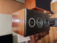
I am resurrecting this thread and my effort to improve a speaker I built. It is an MMT using two Satori MW16P-08 and a 29R tweeter. Crossover and dxt file attached. I have been told multiple times that my XO is the problem. I contacted Madisound and they said that PHYSICAL configuration is not supported by my two-way XO. They said it should either be an MTM or a 2 ½ way.
Other considerations are that I do not have baffle step compensation (Wb = 11.5 inches, Fb=350 hz)
Box dimensions are 11.5x15x22 inches.
I took a stab at a 2 ½ way XO Sim and I am sure I am way off lol. Feel free to offer suggestions to improve it and correct any errors that I have. Your suggestions are appreciated.
Attachments
Surprised no one mentioned the Rinjani? Its an open plan design by Danesian Audio (part of SB) that uses the exact same drivers?
Heard these speakers, they are not forward and in fact a touch laid back.
https://sbacoustics.com/wp-content/uploads/2021/07/Rinjani-User-Manual.pdf

Heard these speakers, they are not forward and in fact a touch laid back.
https://sbacoustics.com/wp-content/uploads/2021/07/Rinjani-User-Manual.pdf
Last edited:
I have been told multiple times that my XO is the problem. I contacted Madisound and they said that PHYSICAL configuration is not supported by my two-way XO.
Neither of these should be an issue. The MW16P and 29R are good partners. Can we look at your existing 'problematic' crossover and baffle layout?
good idea fishball79. At least give a baseline for comparison. I would build one of the SB designs and one of yours so you can compare back and forth in mono.
As long as you don’t establish your own measurement data or at least have some reality check on your imported data (phase info???) your sims are moot. Build the kit!
what i see in your xsim is that there is no compensation for the alignment. That can make a big difference. Are those responses measured in the speaker from the same point? or is it based on factory graphs?
Neither of these should be an issue. The MW16P and 29R are good partners. Can we look at your existing 'problematic' crossover and baffle layout?
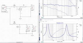
Above are 2 XO. The one on the left is the current 2 way "as built" crossover. The one on the right is proposed 2 1/2 way.
The first question to be answered: is a 2 way for this physical configuration right or wrong?
If it is better with a 2 1/2 way is the proposed even close to what is needed.
That question may be OBE since the SB crossover was published in this thread and I should compare and build the one provided to me. But this is also a learning exercise so I dont repeat my errors. Thanks
Attachments
what i see in your xsim is that there is no compensation for the alignment. That can make a big difference. Are those responses measured in the speaker from the same point? or is it based on factory graphs?
That is a model in XSim. My actuals show a shallow slope down from 400hz to 50 hz. I assume that is an indication of baffle step loss. No?
good idea fishball79. At least give a baseline for comparison. I would build one of the SB designs and one of yours so you can compare back and forth in mono.
Im probably just going to bnuild the other XO provided as we know that works and is proven 🙂
As long as you don’t establish your own measurement data or at least have some reality check on your imported data (phase info???) your sims are moot. Build the kit!
I used the manufacturers data. I will build the Rinjani however I want t learn so that is why I just didnt build it.
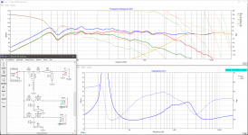
Ok so I went into XSIM and duplicated the Rinjani. Looks very nice in the model. R2 does not seem to have a big effect. it shapes the downward slope on the woofer a bit but wondering is it absolutely necessary or am I missing something.
The first question to be answered: is a 2 way for this physical configuration right or wrong?
Very, very wrong. Two drivers at differing distances from the ear will need individual delay compensation in the crossover. You can look at an alternative topology that uses compound rolloff, aka Zaph ZRT 2.5 way. I find that usually works a lot better for the 'lower' woofer.
If you're set on the Rinjani that's OK. R2 controls the 'knee' of the crossover and is usually not included unless the designer felt it necessary (it usually is).
When you publish or evaluate the crossover, make sure to look at individual driver responses. This gives you (and us) a lot of info about phase behaviour of each driver. The on-axis predicted sum is not the most useful diagnostic tool, as it can also be the result of destructive cancellations, resonance etc.
Note that if you're building the crossover in #64 you have to exactly duplicate the baffle. The baffle is an integral part of the crossover and cannot be altered for a given driver set and crossover.
Note that if you're building the crossover in #64 you have to exactly duplicate the baffle. The baffle is an integral part of the crossover and cannot be altered for a given driver set and crossover.
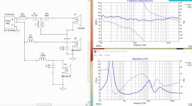
Very true, i thought he would make a straight one so I messed arround for a straight one with the Rijani laout of the front plate and made it phase aligned.
If you don't do it straight (but slanted like the Rijnjani) there is no way to do a crossover right than measuring. Straight you can get close with calculating the delay needed for the driver layout so all drivers are aligned. I did it with the formula in the attached zip, based on the frontplate of the Rinjani, and came to this 2.5 way config (only an example, no guarantee on success as it's on traced response, not measured).
Attachments
hmm.. I figured he would tilt his back at approx. 7 deg. but I seen now that his baffle looks a bit wider too.
What you are coming up against is the limitations of the simulation and measurement process you are using. If you had polar measurements or simulations of the drivers it would be very easy to see the effect on response and directivity that the different crossover types and layouts are having. For anyone that does not have years or decades of experience in understanding this from a practical experience point of view I have a suggestion.The first question to be answered: is a 2 way for this physical configuration right or wrong?
If it is better with a 2 1/2 way is the proposed even close to what is needed.
That question may be OBE since the SB crossover was published in this thread and I should compare and build the one provided to me. But this is also a learning exercise so I dont repeat my errors. Thanks
Use Vituix and follow Kimmo's instructions. Once you have reasonable polar data (preferably measured as you already have the speaker) any combination of layout or crossover can be simulated and compared to see how the on and off axis responses compare. It won't tell you what you like but it will tell you what you will get. This can be done in room with a combination of gated farfield and near field measurements.
VituixCAD help 2.0
https://kimmosaunisto.net/Software/VituixCAD/VituixCAD_Measurement_REW.pdf
- Home
- Loudspeakers
- Multi-Way
- Assistance with Satori 2 way build