Some headphones are designed to have a series resistor in the output. Some standard that I cannot recall specifies 120 ohms, but most headphone amp circuits that I have looked at use a lot less, typically 33 ohms. I suggest you provide one on the PCB as an option.
Paul Bysouth, October 2009
Perhaps we could use a wirewound rheostat (or maybe just a normal pot will do) in this position? This would allow a person to tweak for the best resistor. Maybe just a trimmer that you can set for a specific pair of headphones. From a performance stance, I wouldn't want any at all. But what do I know about sound...
And Hugh, I would like to know who fabricates your PCBs?
- keantoken
Last edited:
Hi KT,
Ourpcb, a Chinese maker of the highest ethics and manufacturing standards. I've been very impressed. They made a mistake on one board recently, and did the entire order again to get it right. They shipped at their expense, too. I'd given them careful instructions in the original order, they acknowledged this, and I was extremely impressed, more than $1k was involved. This is so far ahead of other companies I've used before that I unhesitatingly recommend them.
They have an inexpensive prototyping service too, around $USD60 plus shipping for a panel as I recall. At this price it's not worth doing it yourself.
My understanding of this series resistor is that it is a protection for direct coupled HP amps. Ours is cap coupled, perhaps not needed, but the option does no harm!
Cheers,
Hugh
Last edited:
On that note, Hugh, there is an error on the boards you sent me. I Emailed you about it but did not get a response.
Thank you for the appraisal... I will surely consider them.
- keantoken
Thank you for the appraisal... I will surely consider them.
- keantoken
Aspen Headphone Amplifier
Hugh
International Standard IEC61938 specifies that all headphones should be driven by a 120 ohm source regardless of impedance. Many modern headphones now conform to this. I had been using a 68 ohm series resistor with my Class A headphone anplifier, and it seemed to match earlier headphones very well. However , I now have a pair of Audio Technica W1000 headphones which are 40 ohms according to their specifications, and they do indeed sound much better now that I have changed the series output resistor to 120 ohms. Lower series resistor values with headphones like this will lead to subjectively excessive treble, and poor bass response.
SandyK
Thanks Sandy,
Much appreciated - updated standard, we will comply, 120R it is!
KT,
No error, in fact, the component is mounted on the foil side..... a hole would create a potential short! But thanks for looking, I spent long hours doing that board!
Hugh
Much appreciated - updated standard, we will comply, 120R it is!
KT,
No error, in fact, the component is mounted on the foil side..... a hole would create a potential short! But thanks for looking, I spent long hours doing that board!
Hugh
Revised Mute circuit
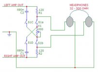
I have revised my mute cicrcuit of several posts ago. I think a better arrangement is as attached. The changes are:
- Moved the output resistor (ie the 120 ohm) to after the mute circuit, and next to the headphone socket, and
- A second socket with its own (different) resistor.
This would allow for quick checking as to whether 120ohm is best or some other value, and also two headphones could be used provided their impedance is high enough (and the two people could agree on the volume).
Paul Bysouth, Oct 2009
Attachments
There's more to the story... Considering this thread, a switchable or variable Zout might be very desirable.
http://rockgrotto.proboards.com/index.cgi?board=review&action=display&thread=2565&page=2
Hugh, this is a demanding project!
- keantoken
http://rockgrotto.proboards.com/index.cgi?board=review&action=display&thread=2565&page=2
Hugh, this is a demanding project!
- keantoken
I vote for dropping the tone control circuit add on.
Canal resonance;
Why does it occur?
Is it solely due to listening with closed back headphones, or with open back headphone, or any headphones, or always there irrespective of headphone usage?
If it's there all the time then our ear brain system has already filtered it out and we hear what is out there. No need for any correction.
Provision for changing the series resistor could be made by using pin receptacles: http://www.leyconn.com/Products/UploadFiles/2007111416451949.pdf
Or here: http://search.digikey.com/scripts/DkSearch/dksus.dll?Detail&name=ED90096-ND
BTW, it seems odd to me that headphones would be designed to have so much series resistance. Why throw away a bunch of the signal?
On the mute switch, why is R2 necessary?
Sheldon
Or here: http://search.digikey.com/scripts/DkSearch/dksus.dll?Detail&name=ED90096-ND
BTW, it seems odd to me that headphones would be designed to have so much series resistance. Why throw away a bunch of the signal?
On the mute switch, why is R2 necessary?
Sheldon
Last edited:
.......
Folks, it's coming along, and looking good. Would someone like to try searching for a suitable CMC, that is, a mains/2 x 6Vac 5VA pcb mount trafo, nice and cheap, from Digikey or Mouser? Something Chinese and widely available would be ideal. Once we have the pinout, we can move ahead with board layout.
Cheers,
Hugh
Use overwound coils, whether a transformer or choke, go straight to hell!
Horses for courses -
http://industrial.panasonic.com/www-data/pdf/AEX0000/AEX0000CE2.pdf
Inexpensive and stocked at digikey. Triad makes similar chokes, but I'm not impressed by their QC.
One might not think they need that differential leakage inductance, given your sims with unreferenced ripple being common mode, but I assure you, in reality, your mains suck. And those dreadful toroidal ps transformers don't help either. Use a flatpack, flatstack, flat whatever semi-toroidal transformer with physically separate windings and limited bandwidth. Available everywhere, from different manufacturers, and sometimes on Fleabay, cheap -
http://www.signaltransformer.com/Data/Datasheets/LP.pdf
FWIW,
Paul
Last edited:
Use a flatpack, flatstack, flat whatever semi-toroidal transformer with physically separate windings and limited bandwidth.
My vote still goes to AC wall wart.
Use overwound coils, whether a transformer or choke, go straight to hell!
Horses for courses -
http://industrial.panasonic.com/www-data/pdf/AEX0000/AEX0000CE2.pdf
Inexpensive and stocked at digikey. Triad makes similar chokes, but I'm not impressed by their QC.
One might not think they need that differential leakage inductance, given your sims with unreferenced ripple being common mode, but I assure you, in reality, your mains suck. And those dreadful toroidal ps transformers don't help either. Use a flatpack, flatstack, flat whatever semi-toroidal transformer with physically separate windings and limited bandwidth. Available everywhere, from different manufacturers, and sometimes on Fleabay, cheap -
http://www.signaltransformer.com/Data/Datasheets/LP.pdf
FWIW,
Paul
Makes sense. This choke?: http://search.digikey.com/scripts/DkSearch/dksus.dll?Detail&name=PLK1302-ND
For PT, something like this?: http://search.digikey.com/scripts/DkSearch/dksus.dll?Detail&name=TX3-20V-ND
Wall transformer is not a bad idea, but would have to be sourced for each country.
Sheldon
Wall transformer is not a bad idea, but would have to be sourced for each country.
Sheldon
I have a 24VDC adapter that uses different interchangeable wall plugs for different countries. I can't find one that is AC only though.
An externally hosted image should be here but it was not working when we last tested it.
Simple working crossfeed
Attached is a simple crossfeed behind the amp which complies to all the requirements posted. Series resistor of 120 Ohms plus cross feed with varing amount with phase change.
This is a constant volume device and crossfeeding will not alter the perceived volume. You can introduce as much phase change as you want by altering capacitor values.
Headphones of any impedance will work equally well.
It remains simple and I take it everyone can figure out what is cutting here.
Nico
Attachments
I have a 24VDC adapter that uses different interchangeable wall plugs for different countries. I can't find one that is AC only though.
An externally hosted image should be here but it was not working when we last tested it.
John, I have absolutely no problem with a wall wart. Some of them are switchmode and followed by a LM317 make a very nice power supply.
After I started using switch mode power supplies in my headphone amps I will never go back to the regular types - You can find pretty high current from these switchmode warts.
I support you on this one completely. Only thing that sounds better than switchmode is batteries - no bull sh!t
Nico
Canal resonance;
Why does it occur?
Is it solely due to listening with closed back headphones, or with open back headphone, or any headphones, or always there irrespective of headphone usage?
If it's there all the time then our ear brain system has already filtered it out and we hear what is out there. No need for any correction.
The ear and transducer form their own small resonance chamber if I understand correctly, not to mention our ears have adapted for sound sources meters away, not right next to our ears.
My only issue with the Wall wart is that it will be a pain carrying 2 separate boxes during moving. Not a huge, horrible problem, but also those things have trouble fitting economically into house sockets and especially power strips (they're so large they tend to cover up two or three sockets).
- keantoken
Okay KT, we do both options walwart input and ac input with small potted pcb mount tansformer. Should not be a problem at all.
I like this! Paul, thank you, the Panasonic 003A with 5R coil DCR and 300mA max current looks good, and will give huge attentuation at 100Hz/120Hz, purpose designed, too.
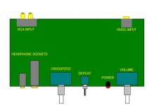
Nico, the crossfeed circuit you incorporated gives 120R series feed, phase change as required (and a couple of sockets could be used to mount the cap, so it can be changed). We need only insert the mute circuit proposed by Paul B. The layout looks very logical; I would propose the output devices sit at the rear, between the RCA inputs and the wall wart input (24V, not 14V, I want more headroom) and bolt up to the rear of the diecast case, so the depth of the pcb and how the controls work on the other side is critical.
I'm ridiculously busy for the next couple of weeks, so will play an abbreviated role. Over to you, Gareth!
Hugh
- Home
- More Vendors...
- AKSA
- Aspen Headphone Amp