Hmmm, thanks Nico!
OK, if that's the consensus I shall go with it. BUT, the project just ramped up in complexity and will take some more time....
I'm very happy to use Meier's approach for the CF circuitry, drive it with an emitter follower, and use a zero fb diamond buffer as output stage.
I will think on this, and come up with something whilst interstate this weekend.
Cheers,
Hugh
Hugh,
my old headphone amp uses an identical topology bar a few component values. I have last night changed the component values and added the 5pF cap to achieve the same order 2H as in your design.
I do not think it is at all necessary to rat-nest it, it sounds warm and easy and articulate, it works fine.
I must stress to the builders of any headphone amp that layout and PSU is of utmost importance as you can hear a lot more buzz and hum from 1 cm than from a couple of meters away from the transducers. Pay a lot of attention to your power supply.
I did not change my BD 139/140 for output devices or 2SA970 at the input instead of 2N5401.
I am not sure if you would call it the typical AKSA sound as you are not a headphone freak and headphones sound and experience is very different from listening to loudspeakers.
A good test for the power supply is to listen to the power rails directly with your headphones decoupled with a cap. It must be dead quiet. Do not think 1 or 2 mV ripple seen on a scope is okay, with my HD800 I can hear it and it will irritate you.
Kind regards
Nico
Hugh,
I do not think that it is necessary to change the topology, it does sound good believe me. My current headphone amp (you have the circuit I think as it is a diamond buffer) and sounds very different. Not better or worse only different. In my humble opinion, the current topology sound characteristics will appeal to many.
I stand to be corrected but Jan Meier has an option of adding the cross-feed at the output and the efect is the same. Do not introduce stuff into the design, it is good as it stands.
Kindest regards
Nico
Last edited:
Hello
Looking at the great number of guy who read this thread (now it's 4,714 times, very popular), they are maby guys who don't speak but want a simple project. So I agree with Nico, we can keep it simple as it is for the first part, and for those who want the Meier's circuit it can be as the second part of the project.
I myself would use the Meier's circuit and the diamond buffer.
Bye
Gaetan
Last edited:
A good test for the power supply is to listen to the power rails directly with your headphones decoupled with a cap. It must be dead quiet. Do not think 1 or 2 mV ripple seen on a scope is okay, with my HD800 I can hear it and it will irritate you.
Excellent tip Nico!

Excellent tip Nico!
Thanks John, I forgot to metion that you have to load the power supply with the idle current because that is when the amp produces no signal and it would be the time you don't want to hear hum or buzz.
Nico
Aspen Headphone Amplifier
In another forum that I am a member of , the Stereophile award winning english designer Graham Slee, presented a crossfeed project for members. There was a lot of initial enthusiasm, but 12 months later, nobody ever mentions crossfeed anymore. The problem is that not all recordings are mixed the same,and the novelty factor soon wears off. Why complicate a perfectly good design unnecessarily ? For that matter, what is so wrong with Hugh's original design ? Many people seem to like it the way it is. By all means give options, but it would be a a shame not to at least try it in it's original guise initially.
SandyK
...you have to load the power supply with the idle current...
Thanks again. I have seen that from my simulations but I haven't done it on a working amp yet.
Hi Sandy,
you are absolutely correct in saying that all recordings are not the same, but one does not crossfeed every thing.
If I want to listen to an album by the Monkees, or almost anything else of the 60's and 70's era with the voices on one channel and the instruments is on another then it does sound very weird. Crossfeed on well recorded albums can spoil it also.
Crossfeed is sometimes essential, but not all the time and my suggestion was an add on rather than design-in. Using 1/8th watt resitors one can build it into a headphone plug adapter and use it when required.
Kind regards
Nico
Member
Joined 2009
Paid Member
If the CF can be added off-board, perhaps with point to point wiring around a CF switch then we have a pretty good option available should we want it.
I believe some people are more sensitive to the issue than others, i.e. they can get headaches if they don't use CF whilst other people don't have an issue. Either way, it needs to be switchable for the user.
Great news that the amp has already been prototyped, no rats nest needed. Let's be confident.
It's time to draw a line under this and move it from the lab to production as they say - or we'll be old to appreciate the sound🙂
Thanks Nico,
Good advice, heartening, and sensible.
What about leave provision for switchable crossfeed on the board? I'm assuming it can be done in low impedance mode at the output?
Hugh
Good advice, heartening, and sensible.
What about leave provision for switchable crossfeed on the board? I'm assuming it can be done in low impedance mode at the output?
Hugh
Hugh,Thanks Nico,
Good advice, heartening, and sensible.
What about leave provision for switchable crossfeed on the board? I'm assuming it can be done in low impedance mode at the output?
Hugh
Yes it can be done low impedance, adjustable by means of a pot may even be better then the user can decide how much cross feed to apply. Although Jan Meier made it extremely scientific, I am of the opinion that just a signal mix is just as apropriate. Fully clockwize is mono while counter clockwize is stereo. Most of the time one cross feeds (mix) only a fraction of the signal.
It can be aplied at the input of the amp as well, this is not brain surgery.
Bigun,
Is the power supply on or off board? Are you looking at a PCB mount transformer or conventional chassis mount. If the transformer is PCB mount remember to include gaurd gaps for safety compliance.
Are you making provision for the large or miniature headphone socket.
Kind regards
Nico
Are you making provision for the large or miniature headphone socket.
I would like both, if space is not a constraint.
Member
Joined 2009
Paid Member
Bigun,
Is the power supply on or off board? Are you looking at a PCB mount transformer or conventional chassis mount. If the transformer is PCB mount remember to include gaurd gaps for safety compliance.
Are you making provision for the large or miniature headphone socket.
Kind regards
Nico
Hugh may find that the decision on psu gets made when he tries to layout the pcb and can see better what works and what doesn't.
My preference is for on-board, there are a number of dual primary (110/230V) low VA pcb-mount transformers available (from Digikey for example) that we could choose. What I'm not sure of yet is whether DIY'ers in other countries requires more flexibility.
Guard gaps - agree. The AC should be isolated at one edge of the board and there are standards for spacing between unrelated signals for safety etc.
Headphone socket - having the provision to install both sizes makes the most sense but I guess individual constructors can choose whether to install one or two.
Nico - you are the closest of all of us to having heard a kind of prototype - anything we should consider as a result ? is the diode bias OK or do we need to include a pot to make it adjustable so that folks who want to build with different heatsinks can do so ?
Nico - you are the closest of all of us to having heard a kind of prototype - anything we should consider as a result ? is the diode bias OK or do we need to include a pot to make it adjustable so that folks who want to build with different heatsinks can do so ?
Hi Bigun,
I am not one for words to describe what something sounds like, all I can say if it makes sense is the sound is warm and inviting, no harshness smooth treble - it does not make your eyes water nor your teeth grate - it is enjoyable. I have been listening to it since late last night, no fatigue.
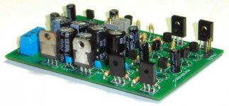
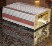
Since I used an existing board some things were fixed, there are two 12V regulators (LM7812/7912) on board and caps are 1000 uF on the input and 470uF on the output decoupled by 47nF.
I never use star ground but only ground plain on both sides of the board, The board is small and fits inside a heat sink pipe. I use a virtual ground and the power supply is remote, 28V switch mode almost identical size to the HP amp box.
I did not want to change the LTP transistors because I favour 2SA970 and output transistors also because I favour BD139/140. The 50 pF (actually 47pF) I used a SMD under the board. My design used diode bias and has been running stable for three years, there is no problem with this config.
I am not absolutely sure how to insert pictures with the new forum but if you tell me I will post some pictures of this amp.
I am quite happy to say that Hugh's design is stable and capable of delivering a very pleasant and engaging listening experience.
Kind regards
Nico
An externally hosted image should be here but it was not working when we last tested it.
An externally hosted image should be here but it was not working when we last tested it.
I hope it worked
Nico
I am trying again, sorry. What a rigmarole to attach pictures!!!!!!
Attachments
Last edited:
Things that I would have liked when I did this one originally:
1) Pot was PCB mounted instead of wired.
2) HP socket was PCB mounted
3) LED was PCB mounted
4) Input sockets were PCB mounted
5) Power input socket was standard wall wart type and PCB mounted
6) Had a PCB mounted cross-talk pot
7) On/off switch was PCB mounte
Mounting the transformer on the PCB as well would complete the amp and making it a wiz to build. Wiring is a pain in the behind and one should design a DIY boards that are fully functional without having to make a single wire connection.
In my opinion only
Regards
Nico
Nico,
Nothing wrong with your opinion...... quickly, arrange the altar, Nico, you stand on top!!
I thank you for sharing, and yes, you have very nicely attached the photos, very good ones too!!
John,
Small and large headphone sockets are just fine. I agree with Nico, a cross feed could be done at the input, and controlled with a pot.
Gareth,
I'm coming around to this as a power supply.
Single rail, 24V, discrete regulator
TL431 shunt regulator set up with 3K/330R to give 25V at the cathode, driving the base of a sturdy npn series regulator. This duplicated for each channel.
2,200uF off a UFSR diode bridge, then to the series pass transistor.
220uF at the emitter of the series pass, 2 x 30mH common mode choke, then 220uF bypassed with 2.2uF film cap.
I think the cross feed can be done at the input at moderate impedance, keeping cap values low making quality caps cheaper. To cope with varying input impedances, we could interpose a 4.7K resistor at the input and calculate crossfeed values from that.
I hope this is meeting expectation!
Thank you Nico, I will email you privately,
Hugh
Hi Hugh,
sorry if I am becoming obnoxious, but one final comment then I will be quiet.
Could you ramp the power supply. I have had a few nasty experiences switching the amp on while the cans are on my head.
A loud pop in the headphones is very nasty on the ears. If you are intending to use a capacitance multiplier, it would soft start natuarally.
Kindest regards and my congratualtions with an excellent group project.
Nico
- Home
- More Vendors...
- AKSA
- Aspen Headphone Amp