Hi All,
sorry for my bad english !
just buyd a 2nd hand pass, X150.
1st, the sound is great and i hear nothing wrong a this point.
following remarks are made whith and whithout inputs connected.
i have several issues (and concerns):
by measuring the output dc voltage,
left = -310mv right is -60mv. (way off margins) (between + and -)
while powering up or down the amp, the woofers are giving a popping sound. (both channels).
powering on...
while watching the woofers i see them go backwards (max) and after 2 sec they come slowly back to the normal position.
powering off...
while watching the woofers i see them go forward (max) and after 2 sec they come slowly back to the normal position.
measured about a peak of approx 15vdc at these on/off's.
after 1 hour the temp is 40° (left) and 44° (right).
worried about the blob.
i dont hear any relay after powering on/off to prevent this blobbing/popping sound.
can somebody help me please ?
greetings !
Hi,
tnx for fast reply!
i suppose this is written underneat the amp or in te inside pcb ?
at the back there is no tag at all.
tnx for fast reply!
i suppose this is written underneat the amp or in te inside pcb ?
at the back there is no tag at all.
...
if it is needet to open the case for the version,
please let me know so that i can retrieve it.
tnx !
if it is needet to open the case for the version,
please let me know so that i can retrieve it.
tnx !

bingo
happytalian

Pass Labs X150.5 , checking/adjusting offsets ,Iq and gain | Zen Mod Blog
principle is the same
happytalian
Pass Labs X150.5 , checking/adjusting offsets ,Iq and gain | Zen Mod Blog
principle is the same
Hi Zen,
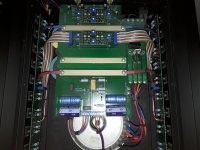
Te resemblance of the pcb's are diffrent and this way very confusing to me.
Other trimmer tags... diffrent placings...
Te resemblance of the pcb's are diffrent and this way very confusing to me.
Other trimmer tags... diffrent placings...
Wayne, zen, ...
you mean the 2 untagged center ones ?
witch pcb is what ?
top/bottem pcb left or richt channel ?
what about the p1 , p2 , p3 and p4 ?
will this regulation solve also the bopping at power on/off ?
sorry for that many questions guys.
just dont wanna make mistakes on this precious piece of equipment.
guys, tnx in advance !
edit… witch measuring pins are what ?
1 near c1 , c2 , c3 , c4.
Last edited:
The two outside pots set the bias. Set very carefully.
On the small board the pot on the side that says Pass is the offset compared to ground. The one on the side that says UGS4 is differential set this first measure from red to black on speakers. Then move one lead to RCA ground and set offset to 0. Go back and forth till both are close to 0. This should reduce noise at turn on and off.
On the small board the pot on the side that says Pass is the offset compared to ground. The one on the side that says UGS4 is differential set this first measure from red to black on speakers. Then move one lead to RCA ground and set offset to 0. Go back and forth till both are close to 0. This should reduce noise at turn on and off.
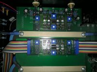
There are 4 sets of pins. Two on the left and two on the right. We used a connector to a voltmeter on these. You don't want to short them be very careful. Each pot on the main board matches up with a set of pins closest to it.
Bias is set at 125mV to start check and set so they are even and temp is 45-50 C
Bias is set at 125mV to start check and set so they are even and temp is 45-50 C

Tnx wayne,
Nice job tagging the pic !
Now,
The 2 left biasses are for the left channel ?
And,...
The 2 small pcb's, the top one is left, the other right channel ?
Gonna try to fix me a second dmm and connectors today.
Greetings
Nice job tagging the pic !
Now,
The 2 left biasses are for the left channel ?
And,...
The 2 small pcb's, the top one is left, the other right channel ?
Gonna try to fix me a second dmm and connectors today.
Greetings
The bias pots match up with each corner and side. Left front for left front side.
Left rear for left year side. The amp-is balanced and has four channels.
Left rear for left year side. The amp-is balanced and has four channels.
Okay,
Bit confusing with those 2 pcb's.
For differential offsets adjusting, i suppose the rear pcb is left channel and the front pcb is the right channel ?
Or way round ?
Bit confusing with those 2 pcb's.
For differential offsets adjusting, i suppose the rear pcb is left channel and the front pcb is the right channel ?
Or way round ?
Would it not be better (more clear to me) to tag each pot and measuring pins accompanied with channels, so that no mistakes could be made ?
Example: left channel offsets.
Offset left diff. OFDIF_L
Offset left abs. OFABS_L
Example: Bias right channel.
BI_POS_R.
BI_NEG_R.
Sorry for my stupid questions guys...
Greetings from belgium.
Example: left channel offsets.
Offset left diff. OFDIF_L
Offset left abs. OFABS_L
Example: Bias right channel.
BI_POS_R.
BI_NEG_R.
Sorry for my stupid questions guys...
Greetings from belgium.
- Home
- Amplifiers
- Pass Labs
- Ask help on PASS X150 dc output differential settings