hi guys, here some measurements:
figured out that pcb at the back is left channel, pcb at the front is right channel.
left dc offset was -27v this to minimum of -15v now (cant turn lower)
left diff voltage was -300mv, now 2 mv.
right dc offset was -15v, this is now -2v (cant turn lower)
right diff voltage was -60mv, now 3 mv.
is this okay ?
bias i cant figure out....
( to be clear, i did NOT change bias current pots)
left bottom is 60mv (underneat the left blue connector.)
left beside c1 is 12 mv.
left beside c2 is 7 mv.
right bottom is 70mv (underneat the right blue connector.)
right beside c4 is 15 mv.
right beside c3 is 6 mv.
here there is something wrong, no ?
greetings,
extra info...
disovered that the woofers 'popping' is only when preamp is connected.
tried to change outlet phase on preamp, didnt improve.
the max measured voltage peak when popping values are about 17 v or so!when preamp is disconnected, those valeus are max 'only' 1.2 v or so.
1 (maybe) important thing is that the amp is not earthed.
dont have an outlet there with earth/ground.
It is not trivial to make these adjustments, and it takes patience.
It looks to me like the whole thing has managed to be un-adjusted at some point.
Are we talking about absolute offsets or differential or both?
The other thing is that the adjustments should be made with inputs shorted to
ground and compared with inputs open, and the difference should be minimal.
The standard for offset on amplifiers like this is around 50mV differential and less
than 1 volt absolute. Both have an influence on whether a preamp connection
creates a thump.
hi guys, here some measurements:
figured out that pcb at the back is left channel, pcb at the front is right channel.
left dc offset was -27v this to minimum of -15v now (cant turn lower)
left diff voltage was -300mv, now 2 mv.
right dc offset was -15v, this is now -2v (cant turn lower)
right diff voltage was -60mv, now 3 mv.
is this okay ?
No the DC is way to high on the left channel.
bias i cant figure out....
( to be clear, i did NOT change bias current pots)
left bottom is 60mv (underneat the left blue connector.)
left beside c1 is 12 mv.
left beside c2 is 7 mv.
right bottom is 70mv (underneat the right blue connector.)
right beside c4 is 15 mv.
right beside c3 is 6 mv.
here there is something wrong, no ?
Doesn't make sense to be the bias is only measured in four places across the 2 pin headers coming out from the board.
greetings,
Hi Nelson,
We are talking about both.
Differentiaal i managed to get at 2 and 3 mv.
The Absolute i managed to lowering but still to high. (-15V left channel).
About the bias...
Even if my measurements doesnt make sense,
The tempetature is stabilised at 48 and 50 degrees c. L/R.
That doesnt seam bad. (After 2 hours)
Still worried to damaging my woofers cause they go to max coarse.
It souds just great, but worried.
Like to solve this...
Thanx for input guys !
Ps: there are 6 points for headers.
Dunno shure what does what...
Ps2: that bopping is with and whithout preamp switched on.
Last edited:
-15 V is from the moon. Now wonder you have such problems. Looks to me
like it is either grossly imbalanced + to - on bias voltage for the Mosfets on the
modules (the pots) or you have no ground reference on the input or it's simply
broken.
like it is either grossly imbalanced + to - on bias voltage for the Mosfets on the
modules (the pots) or you have no ground reference on the input or it's simply
broken.
Seems to me if that offset really was 15V, how can it then 'sounds good, no problems' as the OP stated up front. Maybe it is a measurement error?
Jan
Jan
Hi Jan,
Therefore my question and remark about the 6 measuring points, for whitch measures what...
Measurements where made with 2 fluke dmm's.
Really, it sounds great and even better than my 2 other amps.
The one is the rega elicit_r and the marantz topline sr14mk2 in stereo mode.
If i new exactly what to measure at those 6 headers...
you will know if you invest some efforts in reading post in my blog
physical differences are irrelevant , that's practically the same amp , setting wise
physical differences are irrelevant , that's practically the same amp , setting wise
Zen,
i did read your blog.
i was stuck with the resemblance differenses between my 150 and your 150.5.
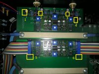
here a pic of the placings of the 6 headers. (with numbers)
left bottom is 60mv (underneat the left blue connector.) (number 5).
left beside c1 is 12 mv. (number 1).
left beside c2 is 7 mv. (number 2)
right bottom is 70mv (underneat the right blue connector.) (number 6)
right beside c4 is 15 mv. (number 4)
right beside c3 is 6 mv. (number 3)
i did read your blog.
i was stuck with the resemblance differenses between my 150 and your 150.5.
here a pic of the placings of the 6 headers. (with numbers)
left bottom is 60mv (underneat the left blue connector.) (number 5).
left beside c1 is 12 mv. (number 1).
left beside c2 is 7 mv. (number 2)
right bottom is 70mv (underneat the right blue connector.) (number 6)
right beside c4 is 15 mv. (number 4)
right beside c3 is 6 mv. (number 3)
Attachments
follow Wayne's instructions how to set relative and absolute offsets , but only after checking and resetting Iq of channels (halves)
see enclosed ,I'm lazy to mark them with more appropriate names , except that L means left side heatsink mounted outputs and R means same for right side heatsink mounted outputs
figure which trimpot on mainboard will invoke change for each 2pin header .... but I can bet that position of them is logical 🙂
use 2wire jack extension as shown in my blog , for measurements , to avoid shorts
set to 940mV at each readout place , in temp. equilibrium
ignore 2pin headers you marked with numbers 1,2,3,4 - they're here for shorting adjacent 100uF caps , for who knows which purpose**
**or - even better - do not ignore 1,2,3,4 , but close all four with jumpers, and short all inputs ( both negative and positive ) to GND, so you'll get what Pa described in post #23
when Iq for each output group is set where it needs to be , you still can't set all offsets where prescribed , time is for Amp Doctor
Attachments

Last edited:
Zen,
great !
you know i didn't notice the IQL2 and the IQR2 headers you marked ?
gee… if i just opened my eyes a bit more...
tnx for tags zen !
adjusting/measuring is not for today anymore cause of other occupations.
you wrote:
"set to 940mV at each readout place , in temp. equilibrium"
i suppose you ment 140mv (like in your blog)
"...between110mV and 140mV ;both readings must be the same"
now the IQL1 and the IQR1 are 70 and 60 mv.
if i raise that to 140 mv, the current will be more than doubled ?
meaning more dissipation, more heat...
now i measured already 50 and 48 degrees. it would be quite hotter, no ?
for the offsets, i followed yours and waynes instructions.
greetz.
Last edited:
you're right ...... 940mV is my mistake and only Papa knows from where it originates 
do as Wayne said in post #15:
edit: if you're chicken from any reason - choose lower Iq reading , but set them all on same number
do as Wayne said in post #15:
There are 4 sets of pins. Two on the left and two on the right. We used a connector to a voltmeter on these. You don't want to short them be very careful. Each pot on the main board matches up with a set of pins closest to it.
Bias is set at 125mV to start check and set so they are even and temp is 45-50 C
edit: if you're chicken from any reason - choose lower Iq reading , but set them all on same number
Last edited:
edit: if you're chicken from any reason - choose lower Iq reading , but set them all on same number
indeed some chicken in me wants to prevent eventual overheating…
double bias voltage probably would mean double the current, double the dissipated power. (now the temps are quite okay i tought…)
1st i'll measure those unmeasured pins (IQL2 and the IQR2 )
maybe they are way wrong. (and not equal)
and depending those values i would take action.
in the meanwhile,
thanx a lot for your help and patience guys !
back with results:
IQL1 was 60mv
IQL2 was 87mv
IQR1 was 70mv
IQr2 was 90mv
adjusted to:
IQL1 is 112,5 mv.
IQL2 is 113,7 mv.
IQR1 is 106,6 mv.
IQR2 is 107,3 mv.
bias pots are super sensitive ! had to turn a tiny hair to change lets say 5mv !
took me a while but setteled.
measurements where a bit less, and stabilized to a little bit higher (to these written values)
the differential offset between the 2 output terminals is now R=12mv L=35mv.
absolute offset between terminals and ground:
right = 5.5 vdc. !
left = 14 vdc. !
oh yes, the temperatures:
after settling, now 2 hours further…
left 47,5 and right 46,6 degrees c.
quite nice !
popping is better.
intresting is > there is no boppin when inputs are shorted.
changing dc absolute offset changes also the IQ values, so it was back and forth adjustment.
at this moment i'm quite satisfied.
of course, could not archieve this without your help guys !
tnx !
Last edited:
5V5 for absolute offset, in temp equilibrium is way too much
14V yikes! much
even if not jeopardising speakers in any way , it eats of dynamic capability of amp - swing is decreased twice that much!
you can't get less with trimpot all the way ?
14V yikes! much
even if not jeopardising speakers in any way , it eats of dynamic capability of amp - swing is decreased twice that much!
you can't get less with trimpot all the way ?
cant get less.
it variatad only lets say about 1 volt plus/minus, so i let'it in the midway of trimmer.
it variatad only lets say about 1 volt plus/minus, so i let'it in the midway of trimmer.
follow Wayne's instructions how to set relative and absolute offsets , but only after checking and resetting Iq of channels (halves)
see enclosed ,I'm lazy to mark them with more appropriate names , except that L means left side heatsink mounted outputs and R means same for right side heatsink mounted outputs
figure which trimpot on mainboard will invoke change for each 2pin header .... but I can bet that position of them is logical 🙂
use 2wire jack extension as shown in my blog , for measurements , to avoid shorts
set to 940mV at each readout place , in temp. equilibrium
ignore 2pin headers you marked with numbers 1,2,3,4 - they're here for shorting adjacent 100uF caps , for who knows which purpose**
If you want DC coupling of course.😉
**or - even better - do not ignore 1,2,3,4 , but close all four with jumpers, and short all inputs ( both negative and positive ) to GND, so you'll get what Pa described in post #23
when Iq for each output group is set where it needs to be , you still can't set all offsets where prescribed , time is for Amp Doctor
You may need new modules if you can't get the DC any better.
- Home
- Amplifiers
- Pass Labs
- Ask help on PASS X150 dc output differential settings