Anybody with money knows heatsinks work best in a vacuum, or a sealed glass bottle of air.

Doing insane stuff to keep sane, sounds almost homeopathic...!
Choosing the Taylor T20 as output tube in a hifi amp is probably a good example of such insanity: As far as I know they were made by one company some 80-85 years ago and has no real equivalents, it consumes 7,5V 1,75A of very clean DC only to heat the filaments and it requires both grid current and a decent amount of negative feedback to produce anything useful. To be perfectly frank, the driver tube could produce the same output power even when wired as a triode, and that without pushing the ratings too much.
Still, when I became aware of the T20/TZ20 tubes less than a year ago I knew I had to get some and build something with them, no matter how impractical they were for the job. It took three power transformers and six chokes to produce the necessary DC rails (and it still hums, though very little...) and three local feedback loops to make these darn things behave as something resembling "normal" triodes. Did I do it because I needed the function of another single-digit power tube amp? No way, I have plenty already. I did it because I saw a picture of a T20 somewhere online and decided that I needed to own it and tame it. Probably a mindset that has caused a lot of grief in the world...
Anyways, the efforts paid off quite well this time, resulting in a nice and quite "neutral" sounding amp. Similar objective results could have been achieved using more traditional tubes (or a couple of LM1875, for that matter) but overcoming a few adversaries always adds some flavour to the dish.
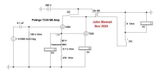
I promised earlier to share some details aboit it, here is a conceptual schematic:
(A technical note: The -30V rail isn't strictly necessary, I had a couple of extra 12V windings on the mains transformers and decided to use them to keep the output tubes biased completely into cutoff until everything has warmed up, since the HV rail uses solid state rectifiers.)
View attachment 1376364
If you want to make it a bit safer you can use E235L instead of EL36 for the cathode follower. same tube but no top-cap
If you want to make it a bit safer you can use E235L instead of EL36 for the cathode follower. same tube but no top-cap
That's an option to consider, yes. I do however like the Frankenstein look of tubes with top caps and I gladly use such tubes whenever I can.
The plate connector will be replaced with properly insulated ones as soon as I remember to order any.
Funny anecdote: I bought a pair of E130L to use as drivers in this amp, not the cheapest tubes around but their high gm should make them excellent cathode followers. Unfortunately I had missed the simple fact that they are much larger than EL36 and won't fit...
I bet these will put up a lightshow when the filaments are lit:

The driver stage is interesting, Dynamic Coupling but with some local feedback from connecting the driver anode to a tap on the OPT rather than to B+.
The prototyping was done with an Edcor transformer that only had a 40% tap which didn't provide very much feedback. Connecting the driver anode directly to the output anode increased the amount of feedback but also decreased max output power by 20% or so. The James OPTs I'm using now has taps at 85% (2.5/3.5k prim Z) that should be just about perfect: a decent amount of local NFB while there is a bit more voltage left across the driver tube when the output anode swings fully negative.
👍
All Triode Distributed Load & Class A2 Positive Biased TriodesThe driver stage is interesting, Dynamic Coupling
The all triode distributed load (UL) circuit is something I looked at about 15 years ago. I had seen in the old tube manuals back more than 60 years ago some rather odd power tubes. These would include the 6AC5 & 25AC5, a pair of very high mu power triodes. Others are 6B5, 6N6G & 25B5, 25N6G.
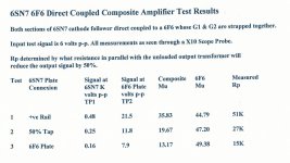
All are now quite expensive, I guess the collectors need them to keep the old stuff running. I wondered about simulating them with easy to get tubes. If one thinks of it, most power pentodes when run as triodes with G1 & G2 strapped together have quite a high mu. I checked some 6F6s in that mode & found mu to be about 50, so OK for some kind of trial. If we check the old tube manuals we find that the recommended driver for the 6AC5 was the 76, a medium mu triode. The 76 is the same as the 6P5G but on the older base.
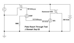
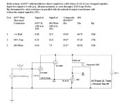
The trial circuit is quite simple, a 6F6 DC driven by the cathodes of parallel sections of a 6SN7GT. The anodes of the 6SN7GT could be alternatively connected to the B+ supply, the OPT CT or the plate connexion of the 6F6. That varies the amount of NFB applied to the anodes of the 6SN7GT. The resulting reach thru to the 6SN7GT cathode is (1/mu). I’ve put the test circuits & results into attachments.
I never did build the complete PP UL circuit. I realized that the driver plate(s) direct to B+ version was used commercially in some radios in the 30s. If you look at the base connexions on the octal 6N6G & 25N6G they are identical to many common power tubes such as the 6F6GT, 6K6GT, 6V6GT & so on. In the circuit they are self biasing, no cathode resistor required. But they did not catch on. Probably more expensive to build these tubes than the corresponding pentodes with there two cathodes, etc. An interesting exercise.
Here are links to a family of tubes suitable for an all triode PP UL amp.
http://frank.pocnet.net/sheets/049/6/6AC5GT.pdf
http://frank.pocnet.net/sheets/127/2/25AC5GT.pdf
http://frank.pocnet.net/sheets/127/6/6B5.pdf
http://frank.pocnet.net/sheets/084/6/6N6G.pdf
http://frank.pocnet.net/sheets/127/2/25B5.pdf
http://frank.pocnet.net/sheets/049/2/25N6G.pdf
Attachments
Gee, I was trained and apprenticed on tubes. Then trained in solid state and learn that in uni. Then trained at distributors and practicing for nearly 50 years.
You know what? Tubes are fun. They can sound pretty good (some awful). Same for solid state. My running systems are all solid state. Why? Cost of running tubes and maintenance, plus I like to crank the heck out of the system I would need a CJ Premier One in the main system, that's 12 x KT88. I ain't paying to retube that monster.
Designed and build both technologies, enjoy both. Have at it!
Yes.... I missed out on that CJ and also an ARC VT200 because of the cost of retubing. Nevermind the heroic size of those beasts... impossible to hide that purchase from the wife.
I have been thinking about an amp with a pair of KT150s though... but that would not be DIY and I don't see many in the market.
The thought of a high power tube amp... DIY... hmm.... sort of scary.... I'd burn the house down, not just the amp.
I am holding onto my ARC D70-II. I had a reputable technician go over the whole thing last year and put nice Svetlanas in it.
Where did you get those cases?
I assume you bolted everything onto a sub plate under the top cover? I need something like that for my current project.
jhstewart9: Yes, your experiments with 6F6 and 6SN7 has been a useful source of inspiration for this project!
I've done similar tests myself using pentode drivers with only the screen grids connected to the output transformers, it worked pretty well but it was difficult to find suitable tubes that could handle large voltage swings on the screens.
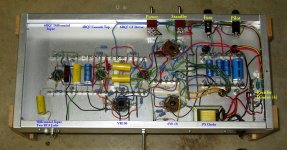
Just as you guessed there are sub chassis below the top plates, made of 2mm alu sheets. Not easy to make everything align but it's nice to get all those screw heads out of sight.
I've done similar tests myself using pentode drivers with only the screen grids connected to the output transformers, it worked pretty well but it was difficult to find suitable tubes that could handle large voltage swings on the screens.
I made them myself from teak planks and 1mm copper sheets. A bit labour intensive but I work night shifts at a mechanical workshop... 😎Where did you get those cases?
I assume you bolted everything onto a sub plate under the top cover? I need something like that for my current project.
Just as you guessed there are sub chassis below the top plates, made of 2mm alu sheets. Not easy to make everything align but it's nice to get all those screw heads out of sight.
Not the same as what I did at all.with only the screen grids connected to the output transformers
Go back, check my schematics carefully & read the text description.🙂
My bad, I didn't mean my experiments were identical, only a version on the same theme.Not the same as what I did at all.
I don't have any means to measure distortion other than looking at the oscilloscope but it seemed to me there was some interesting distortion cancellation going on when the grid current is drawn through the OPT. When the driver anode was connected to B+ the output waveform looked quite horrible but moving it to the 40% tap improved the linearity much more than I would expect from the 3-4dBs of local feedback.
The schematic on p71, is that the final circuit?
On a separate web site I found what looks like the tube mu is 20.
Higher mu means high plate resistance needing HV B+.
The tube could be driven by a 2A3. But the overall expense gets kinda krazy.
Throw money at a project, anything is possible.
On another link I found what looks like the Taylor catalogue from the distant past.
https://www.worldradiohistory.com/A...ylor-Tubes-catalog-and-handbook--34-pages.pdf
I didn't use a distortion paralyzer to measure any of the information on that 6SN7/6F6 experiment.
The TE was SG, DVM & Scope. The objective was to find a way to create a pentode out of two triodes.
That worked very well.
I don't build amps to look at. Or listen to. But I do know how to do a clean build free of problems.👍
Attachments
If you are refering to post 71 in this thread, it is the conceptual schematic of my T20 amp. A completely different story with three separate feedback loops but none that has anything to do with the Triadyne topology.The schematic on p71, is that the final circuit?
That project is finished (except for some hum hunting...), the Triadyne discussion refers to the amp(s) in post 84.
They just got fired up for the first time:
Operating at Zero or near zero bias was common in the 1930's as in Class B Public Address amps or
modulators in AM transmitters. All where fidelity was not important. But they were all PP, no SE at all,
too much distortion. And in PP D% increases at low levels. All covered in great detail in text books
on electronics of that era.
On p84, what is the resistance of the choke in the cathode of the 12B4A?
The Q point of the T220 will depend on that. When the plate of the 12B4A is on the B+ rail, the T220
acts as a Pentode. But when the 12B4A is moved to the plate of the T220, the composite tube acts as a triode.
I see many thick books under your amp. Technical or otherwise?🙂
Operating at Zero or near zero bias was common in the 1930's as in Class B Public Address amps or
modulators in AM transmitters. All where fidelity was not important. But they were all PP, no SE at all,
too much distortion. And in PP D% increases at low levels. All covered in great detail in text books
on electronics of that era.
Yes, I have this idea about building a tube subwoofer amp using class B triodes one day, perhaps something inspired by the Altec 1570.
Perhaps not the most convenient way to produce 100+ watts for a subwoofer but definitely more awe inspiring than chinese class D modules 😎
On p84, what is the resistance of the choke in the cathode of the 12B4A?
The Q point of the T220 will depend on that. When the plate of the 12B4A is on the B+ rail, the T220
acts as a Pentode. But when the 12B4A is moved to the plate of the T220, the composite tube acts as a triode.
The chokes are Hammond 156C, Rdc ~3700 ohms plus another 470R resistor in series, not shown in the schematic. The TZ20 grid sits at +28V or so at idle so there are 6-7mA flowing through the choke and another 7-8mA into the grid. The choke allows the driver to pull the grid below 0V for max output power. A resistor or a CCS connected to a negative rail would probably do the job just as well but I have a certain fondness for iron and copper. Nostalgia for a times long before I was born, I guess.
By the way, the bias is set by a negative voltage on the 12B4A grid. It would probably be possible to find a combination of tubes and voltages that would bias up correctly with the driver grid at ground level but an adjustable bias voltage made things a lot easier.
Mostly fiction I'm afraid, Stephen King and whatnot.I see many thick books under your amp. Technical or otherwise?
Right now I'm trying to figure out how to make the PSU a bit more presentable. I could either pay good money for some better looking iron and build another teak/copper chassis or I could just shove the existing surplus transformers into some kind of anonymous box and be done with it.
First Pass trying to analyze Fuling's T220 SE amp. Got a nice preliminary schematic. B+ needs correcting, might be others.
I had forgot the Electronic Workbench (EWB) simulator does not allow positive biasing of tubes.
But there is another way. I'll run that in a day or two.🙂
I had forgot the Electronic Workbench (EWB) simulator does not allow positive biasing of tubes.
But there is another way. I'll run that in a day or two.🙂
Attachments
Thanks for your efforts, John!
Electronic Workbench, that's something I've barely seen since I used it to sim Nelson Pass´ Zen amps back in highschool.
B+ landed around 290V, a bit lower than I hoped for but I had to add mosfet cap multipliers to get rid of some hum. Also, the OPT is 3.5K:8R with a 2.5k tap that I use for the local feedback.B+ needs correcting, might be others.
Electronic Workbench, that's something I've barely seen since I used it to sim Nelson Pass´ Zen amps back in highschool.
Any worthwhile hobby has an element of nuttiness to it. Hobbies are about entertainment, and which doesn’t come in a single form. For DIY audio, it spans the emotional (music enjoyment, visual look of equipment, craftsmanship pride, indulgence, etc.), to the intellectual (technical learning, creative expression, experimentation, etc.).
Last edited:
Datasheet here: http://www.r-type.org/exhib/abh0317.htmAnybody got a spec sheet on Fuling's T220? THX 👍
I guess it can be seen as something close to an 811A but with lower mu (62) and half the power rating.
just an excellent thread guys. When I get serious about building a product, I often look back in time, like back to the 30-40's for ideas about front panel appearance. But knowing what I know, it is then best to use other people's designs in order to get the desired sonic results that I want. If I had a different last name, then maybe products would move out the door, but it really isn't about sales. I just love what I do and often end up doing it for free.
- Home
- Amplifiers
- Tubes / Valves
- Artistry vs. engineering, or: Are we just nuts?