Already posted over in the GB thread, try my luck here too:
Has anybody 2 PCBs I could buy? Has anybody the knowhow/time to create eagle files from the pictures of the 240mmX107 PCB?
Many Thanks
Sven
I'm on it. None of us German friends of Georg (Permaneder) has his original design, but I'm recreating the PCB layout and gerbers. I'll make them available in the near future.
exactly
or you can install everything , but power up only bias PSUs ,pre-set bias to VFets shut down , then power up main PSU
Nelson mentioned cheap DMMs are great for setting bias. I found some for $5. I imagine that's hard to beat.
DMM Digital Multi Meters
Regards,
Dan

I'm on it. None of us German friends of Georg (Permaneder) has his original design, but I'm recreating the PCB layout and gerbers. I'll make them available in the near future.
Consider contacting the board fabricator of the original GB. They might have the files.
Consider contacting the board fabricator of the original GB. They might have the files.
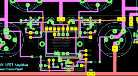
Tadaaaa ! 😀
Here are the Gerbers from Georg - from 3rd June 2014.
I am offering to do one production-run with the PCB manufacturer selected by Georg. They're making high quality PCBs, based in Europe.
However, I don't have the time to run a GB. If someone volunteers, I'll take care of production and would be willing to ship out one package with PCBs per region. Will write more in the original GB thread.
View attachment CSX_SONY_VFET-140530.ZIP
-Oliver
Last edited:
Tadaaaa ! 😀
Here are the Gerbers from Georg - from 3rd June 2014.
I am offering to do one production-run with the PCB manufacturer selected by Georg. They're making high quality PCBs, based in Europe.
However, I don't have the time to run a GB. If someone volunteers, I'll take care of production and would be willing to ship out one package with PCBs per region. Will write more in the original GB thread.
View attachment 447138
-Oliver
hi dsdjoy,
thanks for share the files...
btw are you sure it is the latest version?
i think there are some missing track compared to the latest one.
An externally hosted image should be here but it was not working when we last tested it.
missing line at the jensen transformer.
is that OK..?
Attachments
Just completed my Remote PS with Powercon connectors. I'm hoping it'll be compatible with Part 2's amp to save me from doing it all again!


Regards,
Dan 😱
Regards,
Dan 😱
This impress like weakless part.
For the amp, What you gonna do?
Actually is handsome and massive.
Dokparts from Chinna? I got the same for make my last SE amp. (I am still building)
For the amp, What you gonna do?
Actually is handsome and massive.
Dokparts from Chinna? I got the same for make my last SE amp. (I am still building)
hi dsdjoy,
thanks for share the files...
btw are you sure it is the latest version?
i think there are some missing track compared to the latest one.
An externally hosted image should be here but it was not working when we last tested it.
missing line at the jensen transformer.
is that OK..?
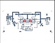
O.K.
that is interesting! I downloaded a Gerber viewer and inverted the bottom side and made a scan of my still unpopulated bottom side pcb and found
yes you are right two longer lines i painted red on the original picture are gone…..
but 🙂 there are instead two small connections in the new layout in the red circles that seem to substitute the long lines….
Please more eyes!
Attachments
I've got problem. One chanel is OK but in the second I'm loosing bias voltage on 2SK82 after switching power on it drops from -11.8V to something like +0.5, at the same time voltage on R11 rise showing high current going through transistors. Bias voltage on 2SJ28 stay resonable high. Reconing I had burnt both Jfets I've change for new pair checking everything many times in the process but the problem is still there. Any idea ? Maybe TL431 is faulty ?
This impress like weakless part.
For the amp, What you gonna do?
Actually is handsome and massive.
Dokparts from Chinna? I got the same for make my last SE amp. (I am still building)
Yes. This is the chassis I purchased for my remote PS.
Full Aluminum Chassis Case Enclosure FOR Preamp Tube AMP DAC 430 80 330mm | eBay
Regards,
Dan 🙂
First time I was a bit patient and observed was was going on. Ids reached almost 8A.I've got problem. One chanel is OK but in the second I'm loosing bias voltage on 2SK82 after switching power on it drops from -11.8V to something like +0.5, at the same time voltage on R11 rise showing high current going through transistors. Bias voltage on 2SJ28 stay resonable high. Reconing I had burnt both Jfets I've change for new pair checking everything many times in the process but the problem is still there. Any idea ? Maybe TL431 is faulty ?
So transistors are lost. Second time I switch off at the first shows after few seconds. Are 2SK82/2SJ28 lost again ? I've got only one additional spare pair of KE-33 grade.
I'm lucky this time ! SITs are OK. I've change bias PSU for external one and it works. Looks like it needs more voltage at the start than standard circuit from article can deliver (I started from -15V/2SK82 this time). So there is need to change resistors values to get that low (or high) in the bias PSU, so as to start from save voltages which block SIT's Ids current. Bias voltages drop a bit while switching main power rails on. Problem arise then they drop to low and trigger high current in the SITs and you don't react for that since you don't know what is going on.
It is handy to use 4 voltage meters at the same time. One for current watching, two for bias voltages, and one for voltage at the output.
It is handy to use 4 voltage meters at the same time. One for current watching, two for bias voltages, and one for voltage at the output.
Hi Diyers
Today audio music sources are with XLR outputs ex :
DAC's, audio cards , digital music servers and hi standard cd players etc....
That way CSX1 amp input with symmetric xlr cables give most supression of noise floor
artefacts by cancelation in opposite phase -60dB.
In theory is work but something new to me most time i am rca user
so next interesting modification for rediscover music albums collection 🙂
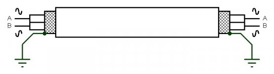
On picture mono symetric cable for balanced input like in CSX1 Vfet amp.
What Yours experience ?
Best regards
Today audio music sources are with XLR outputs ex :
DAC's, audio cards , digital music servers and hi standard cd players etc....
That way CSX1 amp input with symmetric xlr cables give most supression of noise floor
artefacts by cancelation in opposite phase -60dB.
In theory is work but something new to me most time i am rca user
so next interesting modification for rediscover music albums collection 🙂
On picture mono symetric cable for balanced input like in CSX1 Vfet amp.
What Yours experience ?
Best regards
Attachments
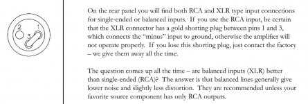
If I recall, the amplifier's input is simply an isolated transformer primary -
you can connect it any way you like.
😎
you can connect it any way you like.
😎
- Status
- Not open for further replies.
- Home
- Amplifiers
- Pass Labs
- Article - Sony VFETs part 1