Lets have it the other way first - how many ASIO channel pairs do you see in ARTA setup, like 1-2, 3-4, etc?
In the meantime I have been able to sketch the input stages of 2i2.
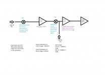
Attached is the block diagram.( If the need arises I can upload the sketch. ) After studying the same and noting that the first stage of line amp is a unity gain buffer,how much would be the error if the gain of the mic preamp is entered as the left channel preamp gain entry in ARTA ?
Attached is the block diagram.( If the need arises I can upload the sketch. ) After studying the same and noting that the first stage of line amp is a unity gain buffer,how much would be the error if the gain of the mic preamp is entered as the left channel preamp gain entry in ARTA ?
Attachments
In the meantime I have been able to sketch the input stages of 2i2.
Attached is the block diagram.( If the need arises I can upload the sketch. ) After studying the same and noting that the first stage of line amp is a unity gain buffer,how much would be the error if the gain of the mic preamp is entered as the left channel preamp gain entry in ARTA ?
Success now depends on where ASIO inputs/outputs are connected in this diagram.
The challenge surpasses my intellectual ability. I guess I will have to go with an external mic pre or use another measurement software unless creators of ARTA come up with a solution.
Thanks for your time.
Thanks for your time.
At least you have tried which is achievement by itself.
You can probably go along with single-channel FFT mode measurements. My observations are that with linear card it doesn't give significant errors compared to dual-channel FFT. In this mode you don't need to have extra input and dual-channel FFT related calibration.
You can probably go along with single-channel FFT mode measurements. My observations are that with linear card it doesn't give significant errors compared to dual-channel FFT. In this mode you don't need to have extra input and dual-channel FFT related calibration.
I do not want to cross-post but this might help...
http://www.diyaudio.com/forums/equipment-tools/220990-arta-box-parts.html#post3297336
Also suggestions/comments welcome...
http://www.diyaudio.com/forums/equipment-tools/220990-arta-box-parts.html#post3297336
Also suggestions/comments welcome...
ARTA in Windows8/32bit
Installed smoothly on Windows 8 . Did not get a chance to really run it.
Got a gut feeling it will run smoothly too.
Installed smoothly on Windows 8 . Did not get a chance to really run it.
Got a gut feeling it will run smoothly too.
ARTA version 1.8.0 is published (see download section).
New features are:
- ARTA has enhanced view of directivity pattern with new "filled contour plot"
- Reference angle for directivity normalization is now user defined
- ASIO driver recognized true 24 bit format of I/O transfer
- ASIO response has been improved
- Calibration procedure has selectable sampling rate: 44100 and 48000 Hz
- Added Phase intercept distortion in ARTA smoothed frequency response window
- Added overlay in ARTA Step response window
- ARTA saves number of averages in IR measurement setup
- Mic. freq. compensation accept only raising frequency points
- New Tool in ARTA: 1/3 octave SPL and loudness time record history
- LIMP has subtract from overlay command (good for removing influence cable resistance)
- LIMP has cable serial impedance compensation
- LIMP has new L3R lossy inductance model of loudspeaker voice coil impedance
- LIMP has better (nonlinear LSE) optimization of TSP estimation
- LIMP has ability to show several target curves,
- LIMP can generate special target curve by pressing F3 in main window - loudspeaker impedance calculated from TSP
- STEPS has corrected *.csv export
- STEPS has new type of measurement: Loudspeaker Maximum SPL vs. Distortion
On support page there are new tutorials for ARTA, STEPS and LIMP in german language.
Merry Xmas
Ivo & Heinrich
Aaah Hvala Ivo at al odlican poklon za moj rodjendan.
Looks like Birthday present (released on my birthday!)
Zega
Looks like Birthday present (released on my birthday!)
Zega

i have bild a measurement box,bild in amp and bild in usb audio interface.
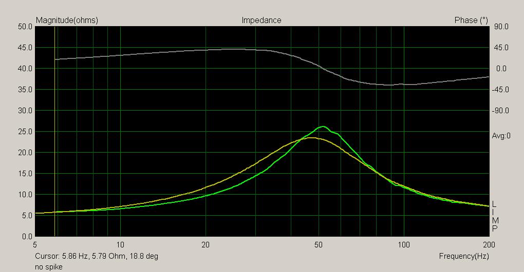
but i'm getting a strange impedance reading.
there is no spike?
also there is some difference between pink noise and stepped sine,but this might be normal.
maybe its a setting?
any help is much apreciated
but i'm getting a strange impedance reading.
there is no spike?
also there is some difference between pink noise and stepped sine,but this might be normal.
maybe its a setting?
any help is much apreciated
Let us take one step at a time. Would you kindly say what were
you trying to measure, what driver, what box volume and similar
details. Are there any manufacturers TS parameters for your driver ?
you trying to measure, what driver, what box volume and similar
details. Are there any manufacturers TS parameters for your driver ?
What is the quoted Qts/Qes/Qms of the driver ? Those curves just look like a driver with a very low Qts.i have bild a measurement box,bild in amp and bild in usb audio interface.
but i'm getting a strange impedance reading.
there is no spike?
also there is some difference between pink noise and stepped sine,but this might be normal.
maybe its a setting?
any help is much apreciated
As for why the stepped sine and noise readings show different curves with different resonance frequencies - that is not an error in the software or measurement, that is the centre frequency and Q of the drivers mechanical resonance changing with suspension excursion! 🙂
All drivers do this to some degree - some dramatically so. The pink noise mode causes less peak excursion for the same overall RMS level thus you get a different (usually higher) resonance frequency.
Welcome to the real world where thiele small parameters are not constant but vary depending on drive level. 🙂
Try reducing the drive level of the stepped sine mode and you will find a point where you get about the same response as the pink noise mode.
Last edited: