Which calibration file do you use guy for capsule Panasonic MW61A?
Do you recommned any other microfone which is better that "home made" pipe with MW61 but relatively not very expensive?
Safos,
Do you recommned any other microfone which is better that "home made" pipe with MW61 but relatively not very expensive?
Safos,
ARTA 1.7.1
Hi,
ARTA 1.7.1 is available on the ARTA homepage (just a service release). (ARTA Download)
Furthermore there is a interesting tool for guys who are performing a lot of polar measurements. It's just a little AutoIT macro, but it makes repetitive measurements much more handier. Thanks to Fabian.
(http://www.fesb.hr/~mateljan/arta/A...ments with script language AutoIT EngRev1.pdf)
Comments and wishes are welcome!
Regards
Heinrich
Which calibration file do you use guy for capsule Panasonic MW61A?
Do you recommned any other microfone which is better that "home made" pipe with MW61 but relatively not very expensive?
Safos,
Hello,
For what it's worth, you may find here attached a calibration file that should be convenient for many cheap electrets capsules.
You'll have to change the extension .txt by an extension .mic before to import it inside ARTA.
BTW : for the French reading people I begun to write several threads about the practical use of ARTA on the french forum of the association "Mélaudia".
See :
MELAUDIA :: forums - mesures
Best regards from Paris, France
Jean-Michel Le Cléac'h
Attachments
Smooth distortion in Step
Hello Ente. I was thinking about smoothing distortion in Step. I think it would in some ways more transparent result. Farina system can be smoothed out, and would help in Step ...
It might be interesting to increase sequence lenght on 512k or 1024.
Richard
Hello Ente. I was thinking about smoothing distortion in Step. I think it would in some ways more transparent result. Farina system can be smoothed out, and would help in Step ...
It might be interesting to increase sequence lenght on 512k or 1024.
Richard
5th and 6th harmonics in the Farina system
Hello Ente, another idea is 5th and 6th harmonics or next in Farina system...
Hello Ente, another idea is 5th and 6th harmonics or next in Farina system...
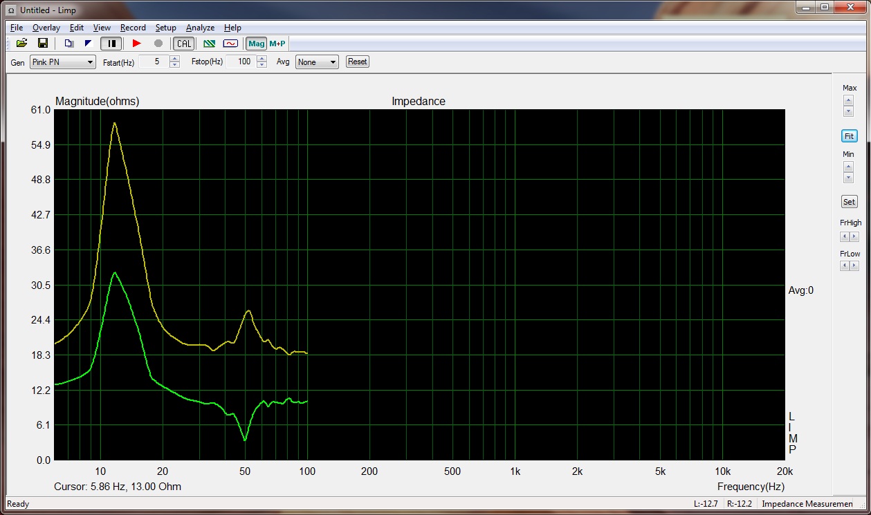
can anyone tel me wats wrong with my setup.
overlay is left channel input,green right
ive used both the onboard audio and an usb audio device.
ive made the setup with 8k2 ohm and the 910 ohm resistors with the zenerdiodes.
and 28 ohm(2x56ohm paralel)
also used 2 different amps.
its an 8 ohm speaker so the value seems to be ok,but the second impedance peak is negetive .green trace
any help would be greatly apreciated.
Last edited:
Your mains electricity is at 50Hz ? (I'm assuming so in amsterdam) It will be some sort of earth loop hum pickup issue.
Are you driving the speaker directly from the sound card via a resistor (in the 33 - 100 ohm range) or via an external power amp ?
By the way, the shape of the main impedance peak is all wrong, (it should be a symmetrical bell curve) so even besides the anomaly at 50Hz there is something very wrong with the measurement setup.
Last edited:
Sorry I just noticed you said you're using an external amp, so earth loop issues most likely are your problem or at least part of it.
If your sound card can drive 33 ohms (most can as thats standard headphone impedance) then simply drive the speaker direct from the sound card via a 33 ohm resistor, (or 68 ohms if your card struggles with 33) with your line input left connected directly to the sound card output and line input right connected to the junction between the resistor and speaker.
Both line inputs should have zener diode protection as shown in the arta docs.
T/S measurements should be done at quite low voltages anyway, so the direct output from the sound card is sufficient, and performing the test at higher cone excursions will introduce inaccuracies.
thank you for responding dbmandrake.
i redid the whole voltage probe thingy ,and now everything is ok.
did a test with a 1% 5.6 and 6.8 ohm resistor ,and it comes close
fyi, the pic i posted in post 127 is a imp measurement of a ht sub.
already did a imp measurement whitout the voltage probe ,for ts parameters,that worked fine.
tnx 🙂
i redid the whole voltage probe thingy ,and now everything is ok.
did a test with a 1% 5.6 and 6.8 ohm resistor ,and it comes close
fyi, the pic i posted in post 127 is a imp measurement of a ht sub.
already did a imp measurement whitout the voltage probe ,for ts parameters,that worked fine.
tnx 🙂
Last edited:
Hello Guy,
To refresh the topic I would like to ask discuss two issue:
- Is anybody who use power amplifier to measure impedance and what is the voltage influence on resonace peak. Soundcard supply about 0,1-0,3 mV but I checked it with small amplifier 2-4V. I Expcected change in fs result but there was not big difference.
- My measurments are higher than technical information of speaker about 20-30Hz. I measured few speaker to avoid mistakes and in all cases look the same. Graph, peak, phase look very good but peak is moved. Do you knw the reasons?
I just found a way of utilizing built-in microphone preamp in Presonus FireStudio Mobile soundcard for dual-channel mode measurements with ARTA. That means dropping the need for separate mic preamp. Is anybody interested?
it could be usefull to share it tnx. 🙂
Ok, have look at the attached guide. I've also sent it to ARTA for review, no comments so far. I hope it doesn't have major faults.
Jānis
View attachment Setting up Presonus FireStudio Mobile for dual-channel measurements.doc
ARTA on FOCUSRITE SCARLETT 2i2 / TASCAM US122
The Focusrite Scarlett2i2 (&TASCAM US 122MkII) is 2in-2out unlike Presonus FireStudio Mobile which has more than 2 ins allowing to connect the way PRTG has described well. Since the mic preamp out is internally connected to line in, resistor R5 cannot be inserted in between. This means proper value for ext left preamp gain cannot be entered in ARTA without having to compromise. ARTA application note no. 1 states on page 6 " There can be other way for the realization of switch box in cases when soundcard has embedded a high quality microphone amplifier (i.e. TASCAM USB-122) or when soundcard has phone output that can drive relatively low impedance. Such cases will be described in other application notes." When can such a note be expected? I emphasize: I do not want to compromise by putting R5=0 and let the 2 channels be driven by different source impedance. Any help in this regard is highly appreciated.
The Focusrite Scarlett2i2 (&TASCAM US 122MkII) is 2in-2out unlike Presonus FireStudio Mobile which has more than 2 ins allowing to connect the way PRTG has described well. Since the mic preamp out is internally connected to line in, resistor R5 cannot be inserted in between. This means proper value for ext left preamp gain cannot be entered in ARTA without having to compromise. ARTA application note no. 1 states on page 6 " There can be other way for the realization of switch box in cases when soundcard has embedded a high quality microphone amplifier (i.e. TASCAM USB-122) or when soundcard has phone output that can drive relatively low impedance. Such cases will be described in other application notes." When can such a note be expected? I emphasize: I do not want to compromise by putting R5=0 and let the 2 channels be driven by different source impedance. Any help in this regard is highly appreciated.
ARTA application note no. 1 states on page 6 " There can be other way for the realization of switch box in cases when soundcard has embedded a high quality microphone amplifier (i.e. TASCAM USB-122) or when soundcard has phone output that can drive relatively low impedance. Such cases will be described in other application notes." When can such a note be expected? I emphasize: I do not want to compromise by putting R5=0 and let the 2 channels be driven by different source impedance. Any help in this regard is highly appreciated.
I'm not familiar enough with Focusrite Scarlett2i2 (&TASCAM US 122MkII), still it may not be necessary to have more than 2 inputs as I'm utilizing only one besides Mic input. Important is the capability to have at least three internal DAW channels and to have ability to separate mic-in and have it mapped directly to one of at least two outputs independently. Not necessarily it should be done through "mute all except mic" (or "solo" for mic-in) setting in mixer. For example, for some cards it could be possible to have routing switch that maps mic-in to main-out or phones-out directly and ignoring the mix completely. Presonus don't have it so I used Mixer as the only mapping choice.
Generally you need to see at least 3 pairs of ASIO (DAW) channels in ARTA but use only 2 of them there and third one leave alone for mic (in isolated way). Then route out- DAW channel defined in ARTA to one output and out-channel of mic-in to the secondary output.
If you're confident that it can't be done with particular card then you'll obviously need separate pre-amp for mic.
I had a quick look on Focusrite answerbase
Have a look what choices you have at The Routing Section for monitor-out and phones-out and see if you have more than one DAW choice here.
Wishing success in either way,
Jānis
ARTA on FOCUSRITE SCARLETT 2i2 / TASCAM US122
From Focusrite Answerbase:
Can I use Scarlett MixControl with the Scarlett 2i2?
No, the Scarlett 2i2 is not compatible with Scarlett MixControl. All of its controls are hardware based instead.
The mic preamp section is supposedly good and I do not want to spend on another mic pre
How about sketching the mic preamp section of the unit, calculate the output impedance and insert the necessary resistor? I think it is built around NJM2122 but the task is daunting as it is completely SMD.