Best excitation signal for small room
In a small room, where we assume low noise and time invariant environment, every signal will give good results, but swept sine gives fastest measurement with descent measurement S/N.
Problem with small room is that you have sparse standing wave room modes and low diffusity field. Such measurement results are very hard to explain in terms of sound quality requirements (flat response, low early reflections). Everyone is left to his own judgement.
Best,
Ivo
Thank you Ivo... I compared the signals to measure impedance under normal conditions, there I went aforementioned results...
Ivo has one question, the best signal to measure in standard, rather small, little fill room.
In a small room, where we assume low noise and time invariant environment, every signal will give good results, but swept sine gives fastest measurement with descent measurement S/N.
Problem with small room is that you have sparse standing wave room modes and low diffusity field. Such measurement results are very hard to explain in terms of sound quality requirements (flat response, low early reflections). Everyone is left to his own judgement.
Best,
Ivo
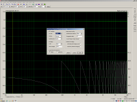
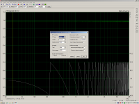
So I'm trying to make sense of the "Propagation delay" setting with an FR2 measurement.
For the first measurement I have a DUT (in the right channel) that has a 1.07mS delay and you can see the appropriate phase response.
For the second measurement I input 1.07mS delay and I expected the phase response to level out. But it's having the opposite effect.
Obviously my objective here is to "zero out" inherent latency of the DUT and allow to evaluate the phase response of other parameters once programmed.
I must be missing a basic setup parameter somewhere?
Thanks,
Dave.
Attachments
Setting of propagation delay
Although you have set up "propagation delay", you still do not get proper phase response probably because you did not put cursor at zero delay sample position, which is sample position 300. - It is most common mistake in measurement of phase response.
ARTA forces shift of "zero time" position to sample position 300 just to allow incorporate pre-ringing response of FIR filtering
Best,
Ivo Mateljan
So I'm trying to make sense of the "Propagation delay" setting with an FR2 measurement.
For the first measurement I have a DUT (in the right channel) that has a 1.07mS delay and you can see the appropriate phase response.
For the second measurement I input 1.07mS delay and I expected the phase response to level out. But it's having the opposite effect.
Obviously my objective here is to "zero out" inherent latency of the DUT and allow to evaluate the phase response of other parameters once programmed.
I must be missing a basic setup parameter somewhere?
Thanks,
Dave.
Although you have set up "propagation delay", you still do not get proper phase response probably because you did not put cursor at zero delay sample position, which is sample position 300. - It is most common mistake in measurement of phase response.
ARTA forces shift of "zero time" position to sample position 300 just to allow incorporate pre-ringing response of FIR filtering
Best,
Ivo Mateljan
Ivo,
I am in the FR2 mode and have no ability to place the cursor at any position.
Are you saying that ARTA is incapable of compensating for a pure time delay in one channel of a measurement in the FR2 mode??
Thanks.
Dave.
I am in the FR2 mode and have no ability to place the cursor at any position.
Are you saying that ARTA is incapable of compensating for a pure time delay in one channel of a measurement in the FR2 mode??
Thanks.
Dave.
Ivo,
I am in the FR2 mode and have no ability to place the cursor at any position.
Are you saying that ARTA is incapable of compensating for a pure time delay in one channel of a measurement in the FR2 mode??
Thanks.
Dave.
It was my bad explanation. I gave explanation for dual channel IR measurement, not for Fr2 mode, where you cant make adjustment by cursor. Sorry, to confuse you.
The propagation delay is just the way to enter time difference in measurement channels. It can be positive or negative value, depending on which channel is used as reference channel. One way to estimate propagation delay, if it exists, is by command 'Record->Crosscorelation/Time delay'.
Best,
Ivo
Ivo,
Thank you. Yes, I understand the operation of the dual channel IR measurement.
For the FR2 mode, I did try to enter a negative value into the "Propagation delay" field but receive the error "Enter a number between 0 and 1000."
With either left/right or right/left reference configuration it still seems impossible to characterize a single-channel time delay in the FR2 mode in this way.
Cheers,
Dave.
Ivo,
Thanks for checking.
I hope I'm being clear on my issue.
What I'm saying is that when performing a transfer function measurement of this type, if the DUT has an inherent delay (and you want to compensate for it) then the compensation for that delay should be placed in the reference channel and not the measurement channel.
This is just a minor detail and not a show-stopper for me. I can easily switch to an alternate program (like SpectraPlus) to perform this type of measurement. All-in-all, ARTA is a terrific measurement suite.
Cheers,
Dave.
Hi Dave,
you are clear now. The problem is compensation of delay in reference channel. To allow that in next version I will allow propagation delay to be positive and negative value.
Best,
Ivo
you are clear now. The problem is compensation of delay in reference channel. To allow that in next version I will allow propagation delay to be positive and negative value.
Best,
Ivo
Hi Dave,
you are clear now. The problem is compensation of delay in reference channel. To allow that in next version I will allow propagation delay to be positive and negative value.
Best,
Ivo
Excellent. Thanks much.
Dave.
Hello,
I´m using Audiotester to get T/S data of some speakers I have and I was a bit worried about some values achieved from it.
So, I downloaded yesterday a demo version of ARTA and tried the T/S LIMP procedure.
Using the same audio interface (Juli@), same ASIO driver, same reference resistor (10 ohms) etc I got a huge variation on Qts (better, and, in my opinion, more realistic, using LIMP).
The difference I saw was the method of measurement of the two programs (pink noise versus frequency scanning).
Any clues about that?
Regards,
And BTW, I´m using the Juli@´s output feeding directly the speaker through the 10 ohms resistor, since it has very high output level.
Best regards
Best regards
Last edited:
@ Ivo: there's a thread where they discuss the possibility to use ARTA with a separate ADC and DAC: http://www.diyaudio.com/forums/equi...sound-card-audio-analysis-14.html#post4415333
You may want to take a peek there.
Jan
You may want to take a peek there.
Jan
And BTW, I´m using the Juli@´s output feeding directly the speaker through the 10 ohms resistor, since it has very high output level.
Best regards
Hi,
10 ohms is very low value for that card.
RCA unbalanced output impedance is 100 ohms.
It has no headphone driver, so you should use impedance at least ten times larger.
Best, Ivo
blmn,
A headphone amplifier (with low output R) might be handy for this purpose. Preferably you'd like Rg to be a low value in Figure 2.1 of the LIMP users manual.
Dave.
A headphone amplifier (with low output R) might be handy for this purpose. Preferably you'd like Rg to be a low value in Figure 2.1 of the LIMP users manual.
Dave.
Tks Davey,
Actually I wass worried about the diference between Audiotester and LIMP measurements, since the reference signal would compensate the impedance issues.
In the figure 2.1, as you shown, the Z value is not dependent on Rg, but I will follow Ivo´s suggestion.
Now I´m thinking it´s not the case and I´ll build a simple amp (maybe an LM3886 unit) to provide low impedance path and maintain the 10R resistor, wich means, I suppose, less noise and interference problems.
Best regards,
Last edited:
Yes, Z is fairly independent of Rg, but Rg (and the external resistor) does determine how the driver is driven across the sweep. With a high value measurement resistor the drive can approach constant current. Some feel this is the best way to measure driver parameters.
I'm not familiar with Audiotester and how it generates T/S parameters.....added mass, driver in a box, or ??. But regardless, I believe LIMP is yielding correct T/S values if the measurement scheme is valid.
Dave.
I'm not familiar with Audiotester and how it generates T/S parameters.....added mass, driver in a box, or ??. But regardless, I believe LIMP is yielding correct T/S values if the measurement scheme is valid.
Dave.
Limp current requirements
Hi,
in measurement of impedance the best S/N is achieved if reference resistor is close to loudspeaker impedance magnitude. ARTA recommend use 27 ohms for that purpose.
We are sometimes interested to find how measured T/S parameters changes with applied measurement current. Reference resistor values from 1 ohms (for high current) to 1000 ohms (for low current drive ) can be used if we have proper amplifier to drive loudspeaker.
On most soundcard line output amplifier are capable to give current for full voltage swing only for impedance larger than 600 ohms. In this case reference resistor should be in range 600-1000 ohms, and only usable excitation signal is stepped sine.
If soundcard has headphone output amplifiers they are capable to give current for full voltage swing for impedance larger than 30-47 ohms. In this case I recommend to use value of reference resistor 47 ohms. Both excitation signal can be used.
If you want to drive impedance with larger current you must connect audio power amplifier that usually can safely drive impedances over 4 ohms.
The value of internal output impedance is not of importance as ARTA encounter its effect on measurement.
Best,
Ivo
Yes, Z is fairly independent of Rg, but Rg (and the external resistor) does determine how the driver is driven across the sweep. With a high value measurement resistor the drive can approach constant current. Some feel this is the best way to measure driver parameters.
I'm not familiar with Audiotester and how it generates T/S parameters.....added mass, driver in a box, or ??. But regardless, I believe LIMP is yielding correct T/S values if the measurement scheme is valid.
Dave.
Hi,
in measurement of impedance the best S/N is achieved if reference resistor is close to loudspeaker impedance magnitude. ARTA recommend use 27 ohms for that purpose.
We are sometimes interested to find how measured T/S parameters changes with applied measurement current. Reference resistor values from 1 ohms (for high current) to 1000 ohms (for low current drive ) can be used if we have proper amplifier to drive loudspeaker.
On most soundcard line output amplifier are capable to give current for full voltage swing only for impedance larger than 600 ohms. In this case reference resistor should be in range 600-1000 ohms, and only usable excitation signal is stepped sine.
If soundcard has headphone output amplifiers they are capable to give current for full voltage swing for impedance larger than 30-47 ohms. In this case I recommend to use value of reference resistor 47 ohms. Both excitation signal can be used.
If you want to drive impedance with larger current you must connect audio power amplifier that usually can safely drive impedances over 4 ohms.
The value of internal output impedance is not of importance as ARTA encounter its effect on measurement.
Best,
Ivo