I'm looking for some feedback on some ARTA testing that I have been doing. I finally feel very comfortable with the software and E-MU 0204 combo.
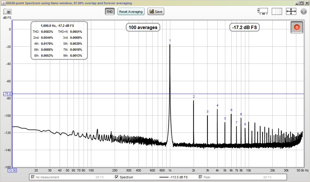
Below is a screen shot of a solid state power amp I have as a test amp for my bench. This image is the amp at 95 watts into 8 ohms.
So I can never really get rid of all the 'grass' on the high end. That does not bother me that much...but I'm curious about the other spikes between the harmonics.
I'm looking for feedback on what I have captured here.
Also, many thanks to RNMarsh, DennisMiller55, Davada and 1audio. Your knowledge, posts and some of your direct emails have been greatly appreciated!
Dave
An externally hosted image should be here but it was not working when we last tested it.
I would think the first thing is to look at the FFT of a loopback signal of the 0204 in your system. Once you determine that is clean you go ahead. What does the 1 watt FFT look like ?
Last edited:
Not to bash ARTA, I use it all the time, but if you want to get distortion numbers I would suggest REW (Room EQ Wizard) using the RTA module as a spectrum analyzer.
For instance I took these measurements of a chip amp when I was trying to reduce ripple and mains feedthrough via the power supply:
For instance I took these measurements of a chip amp when I was trying to reduce ripple and mains feedthrough via the power supply:
The 'STEPS' program part of ARTA gives very accurate FR and distortion measurements. I would suggest you run this with at least a 96kHz sample rate on your sound card to get some baseline distortion v. frequency measurements at your desired output level first.
There's a lot 60Hz power-line harmonics visible in the original post!
There's a lot 60Hz power-line harmonics visible in the original post!
I would think the first thing is to look at the FFT of a loopback signal of the 0204 in your system. Once you determine that is clean you go ahead. What does the 1 watt FFT look like ?
My loop back is clean with low distortion numbers and just a bit of grass above 10K. I don't have a capture of 1 Watt, but I will look next time and compare.
The 'STEPS' program part of ARTA gives very accurate FR and distortion measurements. I would suggest you run this with at least a 96kHz sample rate on your sound card to get some baseline distortion v. frequency measurements at your desired output level first.
There's a lot 60Hz power-line harmonics visible in the original post!
I have used STEPS, just last night I was using the spectrum analyzer portion of ARTA. The 60 Hz noise is from the HP generator I was using. The noise is not there when I use the internal sine generator.
Not to bash ARTA, I use it all the time, but if you want to get distortion numbers I would suggest REW (Room EQ Wizard) using the RTA module as a spectrum analyzer.
I believe I have REW's latest version, I just have not loaded it yet.
What are you using for a voltage divider / interface box for your soundcard?
Thanks everyone!
I Guess your HP Generator needs some TLC... 😉
Review the smoothing caps. And the grounding
Yes. I see line frequency and rectifier-produced harmonics, supply stuff.
Jan
Some of harmonics may be due to quality of load resistor and resistors in voltage divider.
This is what I was thinking about. I'm using a non-inductive load resistor [8 ohms @ 100 Watts] attached to a very large heat sink sitting on the cold floor of my concrete basement.
For the voltage divider, I'm using 1% metal film resistors to create a divide by 10 or divide by 20 ratio.
The harmonics generayed by modern resistors will not be measurable with that hardware. I see lots of ground/usb noise in the plot. Its a common and difficult problem to deal with.
1)tie a seperate ground from the DUT to the computer
2) use differential inputs to the 0204. This means making a passive differential divider to tie to the amp output.
3) explore the ground switch o the bottom of the 0204 (I think it has one).
You still may have problems with the output of the 0204 sharing a ground with the DUT.
These are common problems with USB audio interfaces.
Thanks 1audio.
I am using the balanced inputs on the 0204, but not referencing ground (shield) at all. So obviously, I'm not using a differential divider that would then reference ground. I'll mock one up tonight and measure again.
Both did not make a difference, but I will try again once I build the differential divider since ground will be in play.
Thanks!
use differential inputs to the 0204. This means making a passive differential divider to tie to the amp output.
I am using the balanced inputs on the 0204, but not referencing ground (shield) at all. So obviously, I'm not using a differential divider that would then reference ground. I'll mock one up tonight and measure again.
tie a separate ground from the DUT to the computer
explore the ground switch o the bottom of the 0204
Both did not make a difference, but I will try again once I build the differential divider since ground will be in play.
Thanks!
If your computer is battery operated, try unplugging the charger while doing tests.
I second that which Demian said... and it is usually grounding leakage with test equipment, computer and DUT. Sometimes a ground isolation transformer/filter is helpful.
Thx-RNMarsh
I second that which Demian said... and it is usually grounding leakage with test equipment, computer and DUT. Sometimes a ground isolation transformer/filter is helpful.
Thx-RNMarsh
OK, made some updates:
1) Attached a cable between the chassis / signal ground of the amp and the shield connector of the channel input.
2) Made a true differential voltage divider referenced to ground (Demian, I followed your wiring diagram from the QA400 interface).
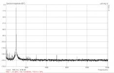
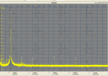
Here are some images with labels. Getting better...
Internal Sine @ 5 Watts
Internal Sine @ 95 Watts
External Generator @ 95 Watts, but I see I forgot to set ARTA to external as I post this.
1) Attached a cable between the chassis / signal ground of the amp and the shield connector of the channel input.
2) Made a true differential voltage divider referenced to ground (Demian, I followed your wiring diagram from the QA400 interface).
Here are some images with labels. Getting better...
An externally hosted image should be here but it was not working when we last tested it.
]Internal Sine @ 5 Watts
An externally hosted image should be here but it was not working when we last tested it.
Internal Sine @ 95 Watts
An externally hosted image should be here but it was not working when we last tested it.
External Generator @ 95 Watts, but I see I forgot to set ARTA to external as I post this.
RNMarsh-I'm on battery power with my laptop.
CharlieLaub-I have REW, just did not have time to load it and use it.
CharlieLaub-I have REW, just did not have time to load it and use it.
Since there is room for error if some details are not clear let me first ask what is mean't by internal and external generator? Looking at the plots from the internal generator the 5W plot suggests everything is -95 dB or lower. The noise is very low really. When the level is increased other spurs appear and that may be normal as power supply harmonics for example. Getting decent measurements below -100 dBC is very difficult. I usually try 4-5 different grounding arrangements between the generator and the ADC with a direct connection and see significant differences.
I do not trust ARTA's distortion calculation since there is not enough data on how its done. I tried it with a source good for -110 dB THD+N and it gave me -85. I think the window around the fundamental may be too narrow for an unsynchronized analog source.
I do not trust ARTA's distortion calculation since there is not enough data on how its done. I tried it with a source good for -110 dB THD+N and it gave me -85. I think the window around the fundamental may be too narrow for an unsynchronized analog source.
ARTA distortion
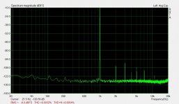
There are two plots. Praxis does not calculate distortion (easily) but ARTA does. However the results from ARTA don't make sense. Both are from the same ADC and show harmonics at around the same levels. ARTA calculates a THD of .000056% (around -130 dB) but a THD+N of 1.64%.
There are two plots. Praxis does not calculate distortion (easily) but ARTA does. However the results from ARTA don't make sense. Both are from the same ADC and show harmonics at around the same levels. ARTA calculates a THD of .000056% (around -130 dB) but a THD+N of 1.64%.
Attachments
but a THD+N of 1.64%.
For my understanding this value looks false 🙄 compared to the image you present..
Hp
- Status
- Not open for further replies.
- Home
- Design & Build
- Equipment & Tools
- ARTA Measurement of Power Amp