The OPA165x have very very high 1/f corner. Some people don’t think it’s a concern in audio but I think the OPA164x is a safer solution.Yes I also went to OPA1642. Still a little unsure about OPA1656/2156 although they do perform very good till now. Must be the CMOS stamp that makes one judge a book by the cover 🙂
I never understood the fixation with ultra low noise, ultra low ripple regs for bulk supply applications. People build these things then run tracks all over the PCB with attendant L and R. You still have to locally decouple anyway. Most small signal circuits draw fairly constant current anyway so big dynamic changes in current are rare (DAC is a bit different of course). I prefer to treat the PSU + the amplifier PSRR as a system. The PSU using say a 78/79xx reg gets you down to a few hundred uV of noise and the amp PSRR and local decoupling does the rest so that the input referred noise is then well below anything of concern in a practical situation.
Circuits with little or no PSRR like a DAC or the front end of a hybrid circuit like the X-Altra MC/MM invariably only draw a few mA, so that’s where you regulate locally and with a very high performance (=low noise and high PSRR) reg.
My 2 cents 😊
Circuits with little or no PSRR like a DAC or the front end of a hybrid circuit like the X-Altra MC/MM invariably only draw a few mA, so that’s where you regulate locally and with a very high performance (=low noise and high PSRR) reg.
My 2 cents 😊

Local regulators is the de facto design philosophy with modern SMD uLDO regulators. One of the reasons one can not find much above 1A. So it makes sense to design with local regulators on 1 PCB and not several PCBs scattered around with added wiring. In the previously mentioned example of the AVCC for ESS DACs I can imagine a separate PCB with LT304x and added wiring will not be optimal in a 100 MHz environment.
When designing/building a single voltage regulator to replace a dreaded outboard wall wart/SMPS of DAC/media player then why not choose what is on the market right now? Those are the LT304x and TPS7A4700 for instance. In such cases LM723 based regulators with pass transistor(s) still do a very good job but at the price of useless heat/lower efficiency.
Even when the application does not ask for using an ultra allow noise regulator choosing such a regulator won't be detrimental either. However, todays challenge is RF and how to keep it out of circuits. When one has no equipment to measure such stuff then simply using those click-on ferrite cores can have surprising effect.
Last edited:
Andrew, you do realize that most here are not interested in logical facts and figures.
Us wants a nice story! 😎
Jan
Us wants a nice story! 😎
Jan
OPA1641 in a variant of the "Didden Reg" 6 years ago.
https://www.diyaudio.com/community/...a-zgf-headphone-amplifier.225577/post-4851725
OPA140 is essentially the same, but available also in SOT23-5.
And for whatever reason, more expensive.
Patrick
https://www.diyaudio.com/community/...a-zgf-headphone-amplifier.225577/post-4851725
OPA140 is essentially the same, but available also in SOT23-5.
And for whatever reason, more expensive.
Patrick
 I must be getting too old for this. I totally forgot that I had changed the AVCC setup in my ES9038Q2M. LT3042 is the regulator but it does not feed AVCC. The following op amp buffer feeds both AVCC and I/V reference. No wonder it sounds so good in subjective sighted listening tests 🙂 But in my AK4490 design LT3042 feeds the Vref directly. That sounds even better
Eh, measures better 🙂 Also a different DAC chip not suffering from "ESS hump" or whatever it is called. Has an A in the name just like TDA which helps.
This is true Jan 🙂Andrew, you do realize that most here are not interested in logical facts and figures.
Us wants a nice story! 😎
Jan
@Bonsai,
Suppose a C-11 regulator output cap is used. In that case you indicated it shouldn't have any adverse effect, is that correct? If so, and if some small-ish audio signal correlated load ripple current is flowing through it at RF frequencies, is the cap nonlinearity fully 100.000% benign, or might it be 99% benign? Just trying to get a little better handle if you were speaking of an absolute effect, a first-order approximation of what you would expect, or maybe something else.
Suppose a C-11 regulator output cap is used. In that case you indicated it shouldn't have any adverse effect, is that correct? If so, and if some small-ish audio signal correlated load ripple current is flowing through it at RF frequencies, is the cap nonlinearity fully 100.000% benign, or might it be 99% benign? Just trying to get a little better handle if you were speaking of an absolute effect, a first-order approximation of what you would expect, or maybe something else.
Sorry, C-II. Class two ceramic for LT3042 output. From page 15 of the datasheet:
The LT3042 requires an output capacitor for stability.
Given its high bandwidth, LTC recommends low ESR and
ESL ceramic capacitors. A minimum 4.7µF output capacitor
with an ESR below 50mΩ and an ESL below 2nH is
required for stability.
Given the high PSRR and low noise performance attained
using a single 4.7µF ceramic output capacitor, larger values
of output capacitor only marginally improves the performance
because the regulator bandwidth decreases with
increasing output capacitance — hence, there is little to
be gained by using larger than the minimum 4.7µF output
capacitor.
Nonetheless, larger values of output capacitance
do decrease peak output deviations during a load transient.
Note that bypass capacitors used to decouple individual
components powered by the LT3042 increase the effective
output capacitance.
On page 16 of the datasheet, they go on to recommend X7R and X5R.
Last edited:
X5R are substandard really. Capacitance varies with DC voltage, they are only low cost. Minimum standard is X7R I think when one desires at least some quality. It is audio so we are picky.
And ... why use a not very cheap but excellent regulator with cheaper caps? It is the opposite of using 78xx with Silmic II.
And ... why use a not very cheap but excellent regulator with cheaper caps? It is the opposite of using 78xx with Silmic II.
Last edited:
Where do you get this? The difference between X5R and X7R is the maximum temperature (XR5 - 85C, X7R - 125C). So X5R is worse only if your application is running at over 85C.X5R are substandard really. Capacitance varies with DC voltage, they are only low cost. Minimum standard is X7R I think when one desires at least some quality.
https://www.allaboutcircuits.com/uploads/articles/TB_captypes_1.JPG (courtesy of Kemet)
Link to article: https://www.allaboutcircuits.com/te....-a-concise-guide-to-ceramic-capacitor-types/
No. An X5R cap in the same value and case size as X7R has more capacitance variation than the X7R. And that at a lower DC bias. That is at least what made me choose X7R as minimum. And preferably only 0805 or larger. 1210 X7R is the weapon of choice for me.
Proof?
I just looked at datasheets of some manufacturers (Samsung, Tayo Yuden, Kemet). No other difference than temperature specified between X5R and X7R.
I just looked at datasheets of some manufacturers (Samsung, Tayo Yuden, Kemet). No other difference than temperature specified between X5R and X7R.
Last edited:
A decent bulk PSU will have a total noise and ripple of <100uV RMS (20Hz - 20 kHz). If your [modern] opamps stages have say 80 dB PSRR at 20 kHz (and 20-30 dB better than that at LF) then the input referred noise will be of the order of 10nV. For a line level stage this is of no consequence. For a very high performance DAC or low noise analog input stage, you can't feed that directly with a supply with 100uV of wideband noise, so use of a local reg is mandatory. On input and output decoupling caps on a local regulator designed to clean up the bulk PSU rails, the change in capacitance with applied voltage is still going to be very small. You can see that when you look at the capacitance vs voltage curves in the LT3042 DS - if you picked off a delta V of 100uV even on the worst dielectric, the change in capacitance would still be negligible (about 10pF on a 10uF cap with a steady DC bias). Keep in mind most small signal circuits draw a near constant current so you are not likely to see big step changes in current - audio DAC's included - but R2R/multiplying types is a bit different.@Bonsai,
Suppose a C-11 regulator output cap is used. In that case you indicated it shouldn't have any adverse effect, is that correct? If so, and if some small-ish audio signal correlated load ripple current is flowing through it at RF frequencies, is the cap nonlinearity fully 100.000% benign, or might it be 99% benign? Just trying to get a little better handle if you were speaking of an absolute effect, a first-order approximation of what you would expect, or maybe something else.
I have not played with the LT3042, but the output noise levels are very low - sub 1uV RMS over a large part of the audio BW - that's excellent good performance and especially so given the wide bandwidth. Adding large decoupling caps on the output doesn't make things better as they explain in the DS because you then sacrifice regulator bandwidth. If you tried electrolytics on the output to get lower noise, you would have high ESL to deal with and a 'peaky' loop response. I guess if you wanted the full wide band low noise LT3042 performance on offer, the layout would be absolutely critical. As a reference point, the reg on the front end of the X-Altra MC/MM sim'd at about 7nV RMS wideband but the reg BW is limited because is uses a 47 Ohm<> 1000uF output filter. Without the filter, the noise is about 130nV.
What about including an estimate of whether or not humans could possibly hear such a thing? Without that what good is an estimate for the magnitude of electrical effect in a dac?
We do know that some humans can hear certain types of effects in dacs at very low levels, yet not hear other things at higher levels. ESS is very clear that there is good experimental evidence for that, and they continue to try to refine their chips to satisfy what they think some audiophiles can hear, not just what is measured at ASR.
The message to me is that we can calculate and measure electronics all we want, but we still need to check audibility experimentally.
Last edited:
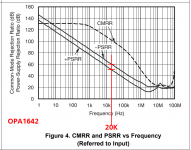
Here is the OPA1642 ; 50 dB PSRR at 20 kHz in the worst caseIf your [modern] opamps stages have say 80 dB PSRR at 20 kHz (and 20-30 dB better than that at LF)
_
Attachments
- Home
- Amplifiers
- Power Supplies
- Are you really fine with IC voltage regulators ?