What do you mean? We were discussing polar response and now you're saying it has little do do with it?
It's a mater of degree. Very sharp edges will affect the polar response while lessor ones effect on the polar response becomes far less. But since there is always diffraction from this edge there will always be an audible effect even if it does not strongly affect the polar response.
You seem to be claiming that there is no diffraction at the mouth edge and that is simply not true. Even with a large radius like mine I can detect a small amount of mouth diffraction.
How would one explain that there are *heaps* of non-roundover waveguides with their excellent polar response ?
Another popular example:
First off, the easiest way to visualize what's happening is with the hornresp wavefront simulator. As they say, a picture is worth a thousand words.
The ability to modify the waveguide termination and see the change in polar response instantly is incredible.
In regards to your question, here's my opinion:
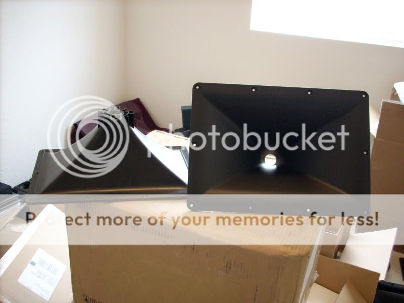
On a loudspeaker, there is a point where the wavefront exits the loudspeaker and enters the room. For instance, I have that QSC waveguide right here, and it measures 36cm across. It has 90 degrees of horizontal coverage.
In order to reduce diffraction, we want the smoothest possible transition from one angle to another. That's what the roundover on the cabinet does; it facilitates a gentle transition from one angle to another. (This is also what the oblate spheroidal waveguide profile does, but at the throat. There's a reason why the OS curve doesn't include a roundover at the mouth, but it has something to do with the formula used to derive the curve, and I don't recall what that reason is. It's also the reason that the profile of the OS curve is dependent on the exit angle of the compression driver.)
The thing that blew me away about the wavefront simulator was the realization that you can have a waveguide that's big enough and deep enough, but if the termination is bad, the directivity is screwed up by the diffraction at the mouth.
For me, this helped explain why some of the waveguides in the 'great waveguide list' didn't perform as well as other waveguides that are the same size. Diffraction is probably the culprit. For instance, I have an 18Sound waveguide in the garage that was bested by the cheap Pyle econowave waveguide. Similar width and depth, the Pyle's directivity was simply more consistent than the 18Sound.
As Bear noted, the QSC waveguide has a gentle transition at the mouth to reduce diffraction. I think there's a few other things that reduce diffraction in horns:
1) The big one is to just use a bigger horn. For instance, the QSC waveguide is 36cm wide. With that width, any wavelength above 944hz will be constrained by the waveguide. That's why we wouldn't expect to see any directivity variation at 2000hz, or 4000hz. It's a big waveguide.
2) I believe that diffraction is a bigger problem in conical horns and waveguides than in other curves. For instance, a LeCleach horn may have 90 degrees of coverage at 1000hz, but only 30 degrees at 5000hz. Due to the broadening of the horn as we get closer to the mouth, the high frequencies are basically 'detached' from the edges.
3) The compression driver will influence this too. Some compression drivers are a better mate for waveguides than others. If the wavefront is screwed up at the throat, there's nothing that can be done to fix the wavefront further down the line.
In the first post of this thread I noted that diffraction appeared to change the directivity of a horn or waveguide. This was a surprise to me, as I'd thought that diffraction treatment was mostly 'icing on the cake', basically something you'd add to a waveguide to make it sound a little more listenable and smoother.
But the wavefront simulator in Hornresp seemed to indicate that diffraction could screw up the directivity of waveguide.
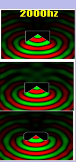
In order to explore this further, I have simulated three different cases:
1) a 90 degree waveguide with no mouth termination whatsoever
2) a 90 degree waveguide that transitions to 180 degrees at the mouth. This is similar to what QSC does in their well regarded 90 degree waveguide.
3) a 90 degree waveguide that transitions to 180 degrees at the mouth, then rounds over all the way to the edge, and *also* has a roundover at the *rear* of the enclosure.
Here's the sims:

Here's some observations about the sims:
The first thing I notice is that the roundover seems to send more energy off axis. For instance, if you look at the second and third case you'll notice that there's more energy radiating *behind* the speaker then in the first case.
For me, the most interesting thing about the sims is that the roundover seems to make the energy level more consistent from left to right. If you look at the first row and then compare it to the third row, you'll notice that a greater percentage of energy is focused into the 90 degree 'cone' in front of the speaker. Whether you think this is a good thing is obviously subjective; some will want the loudspeaker to only project into a narrow angle. But I personally prefer that a waveguide makes the response consistent from left to right. And the roundover seems to facilitate that. (If the simulations are accurate, of course.)
Here's some details on the waveguides:
1) Each waveguide is 36cm wide. This is the same width as the QSC waveguide mentioned elsewhere in the thread.
2) I've only varied the *shape* of the waveguide with the roundover. I did not vary the width. Since I fixed the width, the depth of the waveguides vary. (The unterminated waveguide is the deepest.)
But the wavefront simulator in Hornresp seemed to indicate that diffraction could screw up the directivity of waveguide.
In order to explore this further, I have simulated three different cases:
1) a 90 degree waveguide with no mouth termination whatsoever
2) a 90 degree waveguide that transitions to 180 degrees at the mouth. This is similar to what QSC does in their well regarded 90 degree waveguide.
3) a 90 degree waveguide that transitions to 180 degrees at the mouth, then rounds over all the way to the edge, and *also* has a roundover at the *rear* of the enclosure.
Here's the sims:
Here's some observations about the sims:
The first thing I notice is that the roundover seems to send more energy off axis. For instance, if you look at the second and third case you'll notice that there's more energy radiating *behind* the speaker then in the first case.
For me, the most interesting thing about the sims is that the roundover seems to make the energy level more consistent from left to right. If you look at the first row and then compare it to the third row, you'll notice that a greater percentage of energy is focused into the 90 degree 'cone' in front of the speaker. Whether you think this is a good thing is obviously subjective; some will want the loudspeaker to only project into a narrow angle. But I personally prefer that a waveguide makes the response consistent from left to right. And the roundover seems to facilitate that. (If the simulations are accurate, of course.)
Here's some details on the waveguides:
1) Each waveguide is 36cm wide. This is the same width as the QSC waveguide mentioned elsewhere in the thread.
2) I've only varied the *shape* of the waveguide with the roundover. I did not vary the width. Since I fixed the width, the depth of the waveguides vary. (The unterminated waveguide is the deepest.)
I dunno Bear, foam or felt or something like that which actually extends the profile of the horn, while at the same time rounding and softening it does well pretty well. Inside the horn, maybe not so much.
There were some techniques from the early days that used a rough wall surface to create a cushion of turbulent air right along the walls. Or so went the story. No idea if it actually did anything.
Using foam at the mouth is quite effective- I fabricated a ring of 3/4" foam for my OSWG-style WGs, but think I need to increase thickness somewhat. On the "Econowave" horn a 2" square cross section, modified to roughly track the horn profile, worked wonders.
An externally hosted image should be here but it was not working when we last tested it.
Foaming At The Mouth Article By Jeff Poth
All horns are fundamentally flawed as their distortion is horrific. For Hi Fi horn efficiency is really unnecessary so your paying for that unneeded efficiency is high distortion and so poor sound quality.
In Patricks sims we must notice that in every model there is no baffle! Any baffle modifies sound wave propagation very much!
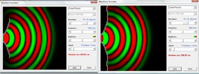
It is possible to add walls (baffle) in Hornresp simulation. Here is a quickie where the wg is 40cm wide an Fq is 1000Hz - the effect is not strong but just try yourselves!
It is possible to add walls (baffle) in Hornresp simulation. Here is a quickie where the wg is 40cm wide an Fq is 1000Hz - the effect is not strong but just try yourselves!
Attachments
Boscoe,All horns are fundamentally flawed as their distortion is horrific. For Hi Fi horn efficiency is really unnecessary so your paying for that unneeded efficiency is high distortion and so poor sound quality.
So far, none of the people listening to the recordings of actual horn drivers made available here:
http://www.diyaudio.com/forums/multi-way/212240-high-frequency-compression-driver-evaluation.html
have mentioned any "horrific distortion", the opposite is in general true, good horn/driver combinations have less distortion than cone/dome tweeters at similar output levels.
Take a listen yourself, please report back as to the SPL level of the various drivers tested where you find the horn's distortion to be audible.
It is true that at high drive levels, compression drivers may have objectionable distortion, but that would be at levels few would use for home use.
And as Earl alluded to, efficiency is not the only reason for horn use, pattern control without resorting to destructive interference (as inherent in arrays of cone/dome tweeters) is a primary advantage gained by the use of horns or waveguides.
Well, you're reducing interference from diffraction, which cannot be consistent from left to right, right?For me, the most interesting thing about the sims is that the roundover seems to make the energy level more consistent from left to right.
In Patricks sims we must notice that in every model there is no baffle! Any baffle modifies sound wave propagation very much!
It is possible to add walls (baffle) in Hornresp simulation. Here is a quickie where the wg is 40cm wide an Fq is 1000Hz - the effect is not strong but just try yourselves!
All nine Sims have four sides.
It may be hard to see because the wall thickness is just 0.74cm
There is a front, a back, and two sides.
The front and back are 36cm wide.
Patrick,...But the wavefront simulator in Hornresp seemed to indicate that diffraction could screw up the directivity of waveguide.
Here's some observations about the sims:
The first thing I notice is that the roundover seems to send more energy off axis.
If you look at the first row and then compare it to the third row, you'll notice that a greater percentage of energy is focused into the 90 degree 'cone' in front of the speaker.
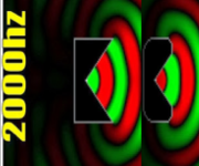
You seemed to have missed a basic rule of directivity, the director has to be large compared to the wavelengths reproduced to have directivity.
Your larger sharp edged "cone" shows it contains just under three wavelengths at 2000 Hz, the smaller rounded cone/horn only two.
Regardless of termination, the smaller horn will show more diffraction surrounding the terminus- a smaller horn will have wider dispersion due to diffraction.
To draw conclusions regarding the effect of roundovers from your sim requires the cone to be the same size prior to the roundover.
Attachments
Last edited:

Patrick,
You seemed to have missed a basic rule of directivity, the director has to be large compared to the wavelengths reproduced to have directivity.
I have always considered this to mean the mouth width more so than the devices length. Although, in this specific case its basically the same thing.
Yup, the bigger Pac man pukes more waves 🙂.I have always considered this to mean the mouth width more so than the devices length. Although, in this specific case its basically the same thing.
Attachments
Badman - your link doesn't provide any measurements! Can you show us some?
Sorry, I can't- I measure to look for specific things, and don't have a good documentation setup. It did reduce the peaking and polar discontinuity below the horn cutoff, substantially, and made a much smoother/cleaner sounding device.
The other thing is that I kinda doubt the "mesh" is large enough. It's a bit like using 2 octave smoothing on a freq response curve... maybe a mesh like 10x larger would start to show some more details?
_-_-
_-_-
Sorry, I can't- I measure to look for specific things, and don't have a good documentation setup. It did reduce the peaking and polar discontinuity below the horn cutoff, substantially, and made a much smoother/cleaner sounding device.
Hey badman,
just wondering how do you know that the differences that you are hearing are the *actual* differences that are occurring? no doubt, it does sound different, maybe even better. but, I'll give you odds that the effects are about nil at the LF end...
_-_-
The other thing is that I kinda doubt the "mesh" is large enough. It's a bit like using 2 octave smoothing on a freq response curve... maybe a mesh like 10x larger would start to show some more details?
_-_-
Each pixel is 0.74cm
At 2khz, each pixel corresponds to 1/23rd of an octave
At 4khz it's 1/11th, etc
That's reasonably high res I'd say. To go higher I'd have to start working with a magnifying glass.
My computer monitor is my tv. It's 55"
- Status
- Not open for further replies.
- Home
- Loudspeakers
- Multi-Way
- Are Most Horns Fundamentally Flawed?