1st picture. Do a quick resistance check (and/or use the diode range on meter) to see if any of the four large BYW diodes reads short.
Beyond that and you must rig up a bulb tester which will allow working on the equipment when its powered and without it blowing fuses. And most important of all... for remote help we need to see the correct circuit diagram.
Beyond that and you must rig up a bulb tester which will allow working on the equipment when its powered and without it blowing fuses. And most important of all... for remote help we need to see the correct circuit diagram.
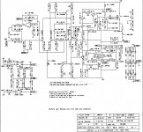
Yes, thanks, I sourced this and was going to look through it for any guidance that it might provide. I gather they have many similarities.
Hi Mooly.
Thanks again. I checked here;- Mastech M-830B Diode Test to make sure I was using my meter correctly.
Bear in mind I am measuring these 'in situ'. From top to bottom, the measurement on the meter was 001, 000, 001, 000.
This measured the same with the positive on the cathode and same readings in other direction.
The meter uses a test voltage of 3 V, and a test current of 0.8 mA for this measurement.
Your link says, the meter will show 001 indicating infinite resistance in the blocking direction and then when the probes are reversed it will read a three digit number to indicate the forward voltage across the diode.Hi Mooly.
Thanks again. I checked here;- Mastech M-830B Diode Test to make sure I was using my meter correctly.
Bear in mind I am measuring these 'in situ'. From top to bottom, the measurement on the meter was 001, 000, 001, 000.
This measured the same with the positive on the cathode and same readings in other direction.
The meter uses a test voltage of 3 V, and a test current of 0.8 mA for this measurement.
If that is the case then 001 followed by 000 does not match their guidance.
Hi Andrew
yes I am confused, but perhaps when the components are still in the board this gives a false reading? Maybe i need to remove them all first. I was measuring across the legs. Same 4 readings with the negative and positive switched over.
yes I am confused, but perhaps when the components are still in the board this gives a false reading? Maybe i need to remove them all first. I was measuring across the legs. Same 4 readings with the negative and positive switched over.
Yes, thanks, I sourced this and was going to look through it for any guidance that it might provide. I gather they have many similarities.
You're welcome. It shows the LM393
You only need to pull one leg of each diode to be able to measure it in isolation.Hi Andrew
yes I am confused, but perhaps when the components are still in the board this gives a false reading? Maybe i need to remove them all first. I was measuring across the legs. Same 4 readings with the negative and positive switched over.
Build up that Mains Bulb Tester (MBT) and power ON.
You will see the 40W bulb switch on to fairly bright. Remember the amp is now LIVE - be careful.
The voltage on the primary will probably be around 5Vac to 10Vac.
The diodes in the bridge should all show some low voltage. The smoothing capacitors should also show a low voltage, maybe as little as 2Vdc.
Power ON via the MBT and measure.
Last edited:
Mind you, as the fuse blows the instant I put power through it that method of testing won't be any use.
The fuse will not pop with a 40, 60 or 100 watt mains filament bulb in series with the supply.
Those diode readings look a little suspect, even for in circuit. 000 and 001 seem to show an almost dead short irrespective of whether the meter is on low ohms or diode range.
Those diode readings look a little suspect, even for in circuit. 000 and 001 seem to show an almost dead short irrespective of whether the meter is on low ohms or diode range.
Sorry, my lack of understanding. I thought the amp had to be powered up for a bulb test in order for their to be something to light up the bulb.
I am surprised they chose a 5534 as the Dc servo.
Any thoughts on why they selected a BJT input that is fairly fast for this duty?
Simply that the designer is of the view that the servo is in the audio path and thus has chosen an audio quality op amp
Sorry, my lack of understanding. I thought the amp had to be powered up for a bulb test in order for their to be something to light up the bulb.
Yes it does but there will be a large voltage drop across the bulb
The bulb goes in series with the live mains feed to the amp.
If the amp has a problem and draws excess current then the bulb can not support that and so the current lights the bulb... all non destructive. If the amp is OK then the bulb can just about manage and the amp will run and the bulb is out.
The reason it works so well is that bulb filament resistance is very non linear with regard to temperature (caused by the current draw).
Check those diodes first though. Reading in circuit can only show catastrophic failure and shorts, but readings of 000 and 001 (for low ohms range and diode range) are certainly that. So make sure.
Testing the old MOSFETs would give some big clues, however it requires a little care:
1) Put the MOSFETs on the table, facing you, label side up
2) Briefly short the leftmost pin to the two other pins. This is to ensure any internal capacitance has discharged and isnt turning the gate on enough to give a false reading
3) Measure from the middle pin to the rightmost pin, both ways around with your probes, and the meter set on resistance
You should see a lowish resistance with black probe on the middle pin, and red probe on the rightmost pin, and infinite resistance when they are the other way around. If you get a low reading both ways around, the MOSFET is shorted.
- Status
- Not open for further replies.
- Home
- Amplifiers
- Solid State
- Arcam Delta 290P keeps blowing fuse