Hello again Eric,
Here is a new case study (or simply a new case)
I took the opportunity of having a piece of EPS in the grade Spedge is talking about in the main thread about DML.
60x80cm 20mm thick (19.6mm more precisely ;-) ).
The 2 modes appear quite clearly (tap/mic @0.22 in torsion)
flexion= 24.7Hz (green), torsion = 44.8Hz (orange)
It comes E = 9.3MPa. I have in my notes 6MPa probably for an EPS without coating (to be checked...)... why not.
And also G = 18.5MPa. Higher than E????
I think the method is applicable but can we use the data in the same way? At firs sight there is not a big difference compare to the plywood except it is not an orthotropic material.
Christian
Christian,
Using the LISA FEM and iterating values of the elastic constants to fit your results as well as possible, I get the following:
E1=6.9 GPa
E2=1.25 GPa
G=0.72 GPa
nu12=0.1
I got these by choosing values of the elastic constants to get as close as possible to:
Torsion mode: 79.5 Hz (model result 79.6)
Saddle (X) mode: 156 Hz (model results 155)
Breathing (O) mode" 161 Hz (model result 160)
Having never tried creating/testing/measuring a Poisson plate before, I was not exactly sure of the best way to determine the Poisson ratio (nu12). But what I observed in the FEM is that nu12 mainly influences the difference in frequency between the saddle and breathing modes. For example, i got the following for various choices of nu12:
nu12 = 0.05: Fb-Fs=156-153=3Hz
nu12 = 0.10: Fb-Fs=160-155=5Hz
nu12 = 0.20: Fb-Fs = 163-153=10 Hz.
I chose nu12=0.1 as it came closest to my best interpretation of your tapping results.
Note, concerning the 145 Hz frequency you observed when you tapped the center and held at the corners, I believe that is the the Breathing mode (160 Hz), but shifted down by the mass of the supports, which are not at the nodes of that mode (in that measurement).
I always check to be sure that a few of the next higher modes observed in tapping are consistent with those predicted by the FEM. It give me more confidence in the result. The next modes in this case predicted by the FEM are shown below, at 223 Hz, 225 Hz, and 391 Hz.
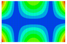
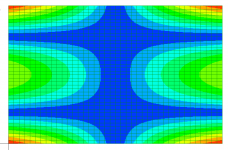
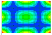
Those resonances do seem to be in your tap results, as for example in this measurement below. The one at just under 200 Hz bothered me a bit at first, as it is so far below the 223 or 225 Hz predicted. But I expect that is the same effect as the 145 Hz one I mentioned above. That is, the supports are not in the ideal position for that particular mode, so the mass of the supports shifts it down. Also note that typically the FEM predicts the higher modes at higher frequencies than are experimentally observed. This is due to the fact that the FEM (mine anyway!) uses the Euler beam equation. At higher frequencies this simplification becomes less valid. Thicker plates are even more affected by this simplification than thin ones.

Overall, I think we have a pretty decent fit to your results here.
Eric
Using the LISA FEM and iterating values of the elastic constants to fit your results as well as possible, I get the following:
E1=6.9 GPa
E2=1.25 GPa
G=0.72 GPa
nu12=0.1
I got these by choosing values of the elastic constants to get as close as possible to:
Torsion mode: 79.5 Hz (model result 79.6)
Saddle (X) mode: 156 Hz (model results 155)
Breathing (O) mode" 161 Hz (model result 160)
Having never tried creating/testing/measuring a Poisson plate before, I was not exactly sure of the best way to determine the Poisson ratio (nu12). But what I observed in the FEM is that nu12 mainly influences the difference in frequency between the saddle and breathing modes. For example, i got the following for various choices of nu12:
nu12 = 0.05: Fb-Fs=156-153=3Hz
nu12 = 0.10: Fb-Fs=160-155=5Hz
nu12 = 0.20: Fb-Fs = 163-153=10 Hz.
I chose nu12=0.1 as it came closest to my best interpretation of your tapping results.
Note, concerning the 145 Hz frequency you observed when you tapped the center and held at the corners, I believe that is the the Breathing mode (160 Hz), but shifted down by the mass of the supports, which are not at the nodes of that mode (in that measurement).
I always check to be sure that a few of the next higher modes observed in tapping are consistent with those predicted by the FEM. It give me more confidence in the result. The next modes in this case predicted by the FEM are shown below, at 223 Hz, 225 Hz, and 391 Hz.


Those resonances do seem to be in your tap results, as for example in this measurement below. The one at just under 200 Hz bothered me a bit at first, as it is so far below the 223 or 225 Hz predicted. But I expect that is the same effect as the 145 Hz one I mentioned above. That is, the supports are not in the ideal position for that particular mode, so the mass of the supports shifts it down. Also note that typically the FEM predicts the higher modes at higher frequencies than are experimentally observed. This is due to the fact that the FEM (mine anyway!) uses the Euler beam equation. At higher frequencies this simplification becomes less valid. Thicker plates are even more affected by this simplification than thin ones.
Overall, I think we have a pretty decent fit to your results here.
Eric
And also G = 18.5MPa. Higher than E????
I think the method is applicable but can we use the data in the same way? At firs sight there is not a big difference compare to the plywood except it is not an orthotropic material.
Christian,
I agree that EPS should probably be isotropic, or nearly so. But why not simply do the flex test in both orientations, just to confirm?
And you are correct to questions G>E, it can't be so. At most, it can only be E/2.
I suspect you have a torsion mode below 20 Hz hat you can't see.
Lower frequencies are harder to get accurately with the RTA/Spectrum in REW, but if you increase the FFT length to 128 or 256 it will help the resolution but slow the updates.
You could also cut a smaller piece.
Eric
Christian,With that E1 = 6.2GPa, E2 = 1.15GPa, E = (E1.E2)^.5 = 1.7GPa
I don't think (E1*E2)^0.5 is a meaningful number, is it? Have you seen this used somewhere before? I don't know what the physical interpretation of that number might be.
If we consider E1 and E2 vectors, then I can imagine taking the vector sum: (E1^2+E2^2)^0.5, but even that I don't think has any physical meaning.
My best guess is that you want a single E to put into the E/rho^3 efficiency factor. But honestly I don't know the right way to approach that question.
Normally I just calculate both E1/rho^3 and E2^rho^3 and figure I'll get something in between!
Eric
Yes, I agree. In fact, the Resonalyser method from the Wiki article actually uses three samples, as you probably noticed. A long narrow one in each direction to get the flexural modes and determine E1 and E2, and a third one (Poisson plate) to get G and Nu.A good practice might be to have 2 samples with 2 different form ratios (length/width) for such tests.
Another one is to measure with precision the thickness!
I found I could usually get E1, E2 and G from a single sample, which allowed me to get the results without cutting my plates into smaller pieces! I'm not eager to do that with some plates, like my carbon balsa plates, which take a lot of work to make. But if you have spare material, multiple samples of different sizes would help give you more data and hence more reliable results.
Eric
Christian,All of that make me considering how a panel is suspended with a new eye... and how it modifies the modes. From memory I would list 5 types of suspensions (probably more if I go back to all the panels listed at least in the history file)
- strings at the corner
- strings some where near the corner on the short side (0.22 point)
- foam all around
- foam located in the 0.22 point area on the vertical long side
- 1 central point at the top short side, 2 points at the bottom short side
There is no doubt that the suspension method is absolutely critical. In the low frequency range, I would argue that the suspension method, (in combination the size, aspect ratio and elastic properties) is the most important aspect of any design. That is to say, since the suspension method determines the modal frequencies, and the modal frequencies determine the frequency response, the suspension method is absolutely critical.
But of course, there are an infinite number of suspension methods. It is an area of great interest to me. As you may know, I don't really care for "hanging from strings" for any actual speaker, except if you are not concerned about low frequency response at all, like say, for a tweeter. Of course, hanging from strings is perfect for characterization of elastic properties.
You have left out variations of the "foam" support such as foam on 2 sides only. Opposite sides or adjacent sides? Long sides or short sides? Three sides?
Further, you could do clamped edges on any number of edges, and in combination with other edges with foam support, or free.
I have discovered recently that even using different types of foams around the perimeter can have a pretty dramatic effect. A hard foam with a wide surface acts more like a clamped edge, while soft thin foam acts more like simple/hinged edge. Just changing the foam I have shifted fundamental from about 75 Hz to 120 Hz for very similar panels. Not to mention how much the damping varies between different foams and the effect that has.
Eric
For now, I am not able to make a link between the modes from simulation you show and the naming of the modes with the 2 integers (m,n). Torsion, flexure, saddle... many names. Do all occur in a DML?
Then we can imagine different criteria to classify the suspension solution :
- the lowest fundamental
- the best modes density
- the capacity to keep the membrane flat... it was the one that leads me for the plywood panel seeing how it warps after a varnish layer.
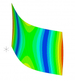
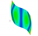
The conventional naming of the modes that I have referred to in the past (1,1), (1,2), etc, has only been with respect to plates with all four edges either simply supported (hinged) or clamped. I'm afraid I don't know if there is a convention for naming of the modes of free hanging panels. Lots of funky modes can happen. What to call this for example?
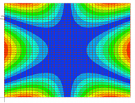
Probably one of the most important questions also is "which of the modes actually contribute to the output?". For the simple or clamped plates we know it's the odd,odd modes. But what about for the free plate? My guess is that modes that include identically shaped areas moving out of phase with each other would not contribute much, while those without such "symmetry" would not. Hence, I would imagine the fundamental torsional mode would ineffective, while the bending modes like the first one below might contribute, while the second would not. Because for the second one, for every point on one half of the panel moving in one direction, there is a second point on the other half of the panel that is moving at exactly the same speed but in the opposite direction. At any distance, the effect of these two points on the motion of the air would be cancelled, I suspect. But this is only me speculating.
Eric
Hello EricChristian,
Using the LISA FEM and iterating values of the elastic constants to fit your results as well as possible, I get the following:
E1=6.9 GPa
E2=1.25 GPa
G=0.72 GPa
nu12=0.1
I got these by choosing values of the elastic constants to get as close as possible to:
Torsion mode: 79.5 Hz (model result 79.6)
Saddle (X) mode: 156 Hz (model results 155)
Breathing (O) mode" 161 Hz (model result 160)
Having never tried creating/testing/measuring a Poisson plate before, I was not exactly sure of the best way to determine the Poisson ratio (nu12). But what I observed in the FEM is that nu12 mainly influences the difference in frequency between the saddle and breathing modes. For example, i got the following for various choices of nu12:
nu12 = 0.05: Fb-Fs=156-153=3Hz
nu12 = 0.10: Fb-Fs=160-155=5Hz
nu12 = 0.20: Fb-Fs = 163-153=10 Hz.
I chose nu12=0.1 as it came closest to my best interpretation of your tapping results.
Note, concerning the 145 Hz frequency you observed when you tapped the center and held at the corners, I believe that is the the Breathing mode (160 Hz), but shifted down by the mass of the supports, which are not at the nodes of that mode (in that measurement).
I always check to be sure that a few of the next higher modes observed in tapping are consistent with those predicted by the FEM. It give me more confidence in the result. The next modes in this case predicted by the FEM are shown below, at 223 Hz, 225 Hz, and 391 Hz.
View attachment 1035121View attachment 1035122View attachment 1035123
Those resonances do seem to be in your tap results, as for example in this measurement below. The one at just under 200 Hz bothered me a bit at first, as it is so far below the 223 or 225 Hz predicted. But I expect that is the same effect as the 145 Hz one I mentioned above. That is, the supports are not in the ideal position for that particular mode, so the mass of the supports shifts it down. Also note that typically the FEM predicts the higher modes at higher frequencies than are experimentally observed. This is due to the fact that the FEM (mine anyway!) uses the Euler beam equation. At higher frequencies this simplification becomes less valid. Thicker plates are even more affected by this simplification than thin ones.
View attachment 1035129
Overall, I think we have a pretty decent fit to your results here.
Eric
That's good that simulations and tests match pretty well. The values you use for E1, E2, G are not very different from the one from the IET formulas give.
I am not sure about the mass of the support as an explanation. The clothespin I use are not the standard one but very small one (25x7x2mm) used in decoration. The string is light also.
I don't know if I will do the test but do you think that to drill a small hole (2mm?) near the edge can replace the support avoiding the question of mass?
For the XPS, as it is thicker than the plywood, the clothespin can't open enough so I use some trips of tape to reduce the thickness for the mini clothespins. A better practice might be perhaps to use only tape and string?
Christian
Eric,Christian,
I agree that EPS should probably be isotropic, or nearly so. But why not simply do the flex test in both orientations, just to confirm?
And you are correct to questions G>E, it can't be so. At most, it can only be E/2.
I suspect you have a torsion mode below 20 Hz hat you can't see.
Lower frequencies are harder to get accurately with the RTA/Spectrum in REW, but if you increase the FFT length to 128 or 256 it will help the resolution but slow the updates.
You could also cut a smaller piece.
Eric
Flex test using the embedded beam configuration is what I did when I bought this EPS..; only in one direction because I didn't want at this time cut the panel. It gives me E=6MPa comparing to the 9.3MPa evaluated with the tapping method.
For G, I don't know an alternative method to the tapping one.
The RTA is set to 65536 for the FFT and 48kHz as sampling frequency. Are are the spectrum. Some filters are probably acting in the range 2 to 20Hz. Anyway, the shape is here.
An other good practice is to be prepared for cutting a second sample (see the XPS case) to readjust the frequencies.
Hello again Eric,Christian,
I don't think (E1*E2)^0.5 is a meaningful number, is it? Have you seen this used somewhere before? I don't know what the physical interpretation of that number might be.
If we consider E1 and E2 vectors, then I can imagine taking the vector sum: (E1^2+E2^2)^0.5, but even that I don't think has any physical meaning.
My best guess is that you want a single E to put into the E/rho^3 efficiency factor. But honestly I don't know the right way to approach that question.
Normally I just calculate both E1/rho^3 and E2^rho^3 and figure I'll get something in between!
Eric
I don't remember exactly where it is but it comes from some paper dealing about soundboard in instrument. !the piano soundboard thesis?
You are right, the idea is to approach data like efficiency.
Christian
Eric,Christian,
There is no doubt that the suspension method is absolutely critical. In the low frequency range, I would argue that the suspension method, (in combination the size, aspect ratio and elastic properties) is the most important aspect of any design. That is to say, since the suspension method determines the modal frequencies, and the modal frequencies determine the frequency response, the suspension method is absolutely critical.
But of course, there are an infinite number of suspension methods. It is an area of great interest to me. As you may know, I don't really care for "hanging from strings" for any actual speaker, except if you are not concerned about low frequency response at all, like say, for a tweeter. Of course, hanging from strings is perfect for characterization of elastic properties.
You have left out variations of the "foam" support such as foam on 2 sides only. Opposite sides or adjacent sides? Long sides or short sides? Three sides?
Further, you could do clamped edges on any number of edges, and in combination with other edges with foam support, or free.
I have discovered recently that even using different types of foams around the perimeter can have a pretty dramatic effect. A hard foam with a wide surface acts more like a clamped edge, while soft thin foam acts more like simple/hinged edge. Just changing the foam I have shifted fundamental from about 75 Hz to 120 Hz for very similar panels. Not to mention how much the damping varies between different foams and the effect that has.
Eric
First may I rephrase to be sure to follow your thinking... Do you have already rejected the string suspension method by the short side because it cancels low frequency modes (or shift them to high?) ?
I am not in favor of this method more for basic mechanical aspects : the panel is not maintain in the different directions, difficult to avoid mechanical strength on the coil in case of spine, the panel can warp...
My plywood panel which works quite well for me has a 17x17mm light foam.
To evaluate the impact of the suspension, you mention 2 steps : without/with the suspension. With the tapping method I see how it is possible to evaluate the modes with the suspension... but without which method do you recommend, The panel has to be maintain in some way.
I am wondering also about damping. It is one starting point of my question about the modes. Panels show a hump in the 200...300Hz. Is it a too strong reflection ?
Christian
Christian
It makes sens EricThe conventional naming of the modes that I have referred to in the past (1,1), (1,2), etc, has only been with respect to plates with all four edges either simply supported (hinged) or clamped. I'm afraid I don't know if there is a convention for naming of the modes of free hanging panels. Lots of funky modes can happen. What to call this for example?
View attachment 1035156
Probably one of the most important questions also is "which of the modes actually contribute to the output?". For the simple or clamped plates we know it's the odd,odd modes. But what about for the free plate? My guess is that modes that include identically shaped areas moving out of phase with each other would not contribute much, while those without such "symmetry" would not. Hence, I would imagine the fundamental torsional mode would ineffective, while the bending modes like the first one below might contribute, while the second would not. Because for the second one, for every point on one half of the panel moving in one direction, there is a second point on the other half of the panel that is moving at exactly the same speed but in the opposite direction. At any distance, the effect of these two points on the motion of the air would be cancelled, I suspect. But this is only me speculating.
View attachment 1035159 View attachment 1035161
Eric
I'm not sure that reducing the mass of the supports will do it. It could help. For me the best approach is to be as sure as possible to place the supports at the nodes. But that may take some experience and trial and error, and ieally having FEM to help figure out where they might be.I am not sure about the mass of the support as an explanation. The clothespin I use are not the standard one but very small one (25x7x2mm) used in decoration. The string is light also.
I don't know if I will do the test but do you think that to drill a small hole (2mm?) near the edge can replace the support avoiding the question of mass?
For the XPS, as it is thicker than the plywood, the clothespin can't open enough so I use some trips of tape to reduce the thickness for the mini clothespins. A better practice might be perhaps to use only tape and string?
Christian
Eric
Eric,
First may I rephrase to be sure to follow your thinking... Do you have already rejected the string suspension method by the short side because it cancels low frequency modes (or shift them to high?) ?
I am not in favor of this method more for basic mechanical aspects : the panel is not maintain in the different directions, difficult to avoid mechanical strength on the coil in case of spine, the panel can warp...
My plywood panel which works quite well for me has a 17x17mm light foam.
To evaluate the impact of the suspension, you mention 2 steps : without/with the suspension. With the tapping method I see how it is possible to evaluate the modes with the suspension... but without which method do you recommend, The panel has to be maintain in some way.
I am wondering also about damping. It is one starting point of my question about the modes. Panels show a hump in the 200...300Hz. Is it a too strong reflection ?
Christian
I agree with all of your reasons for avoding the strings method. But the main reason for me is that when I have tried it, the FR response is always poor in the low frequency range. Recently, I was testing a panel with foam around the perimeter and got very smooth response above about 100 Hz. But with the very same panel, suspended from strings, the response was virtually nil until 200 Hz. I don't know for sure the reason, but I suspect it has to do with the efficiency of the modes in suspension.
Let me explain my thinking around testing and suspension. I do tap testing for both free panels (hanging from strings) and fully mounted/suspended panels. The purpose of testing the free panels is only to determine the elastic properties of the panels. Then, using those properties in the FEM, I can model different designs with various aspect ratios and perimeter conditions (simple, clamped, etc) until I have a design which produces a promising set of modes (mode shapes and frequencies). Then, after constructing a speaker per the design (sans exciter), I retest the panel with tap testing. This time the purpose is to see how close the actual speaker design comes to what I envisioned in the design. Finally, I attach an exciter and do REW testing, to see if the collection of modes created actually combine as well as I had hoped! Sometimes I even play music, if you can believe it!
Eric
Eric,
Flex test using the embedded beam configuration is what I did when I bought this EPS..; only in one direction because I didn't want at this time cut the panel. It gives me E=6MPa comparing to the 9.3MPa evaluated with the tapping method.
For G, I don't know an alternative method to the tapping one.
The RTA is set to 65536 for the FFT and 48kHz as sampling frequency. Are are the spectrum. Some filters are probably acting in the range 2 to 20Hz. Anyway, the shape is here.
An other good practice is to be prepared for cutting a second sample (see the XPS case) to readjust the frequencies.
View attachment 1035286
Curious. Assuming the panel is nearly isotropic, the torsion mode should fall just below the lower of the two bending modes, for this shape of panel, regardless of the poisson ratio, according to my FEM. I wonder if the bump at about 18 isn't it. If you have extra material, I'd try a smaller plate.
Eric
I found this article about tone tuning the violin plates (front and back):
https://platetuning.org/html/resonances_of_violin_body.html
https://platetuning.org/html/resonances_of_violin_body.html
Interesting. Similar technique. Thank youAlso some video measuring the resonance of the violin body and plate tuning:
In the main thread about DML, I answered to a question about the tension of my canvas panel. I use Audacity also. Now that I have tested the technique proposed by Veleric, REW is more convenient.
@Veleric
Eric,
In my posts, you have perhaps noticed that I try to understand why my second panel didn't work. No bass, no treble. It was a 60x80cm panel made of XPS 9mm. The one I use for testing. On this panel I use the same surround foam than in my plywood panel : a 17x17mm "light" foam on the 4 sides. This technique (and foam) seems working with the plywood, not for the XPS. Have you already tried to put some data on the suspension in regard to the panel characteristic? In other words, I wonder if the stiffness of the foam I used is not too high for the XPS while it is acceptable for the plywood?
Writing that and putting to gather recent measurements and older one... I have doubts... Is there a full improper use? When in parallel you say you get a response down to 100Hz... I would say yes, some thing is wrong.
The three upper trace are at close proximity of the exciter in order to give an idea of the mode at the exciter
The three lower at 2m (far!)
green / dark green are a 20x60cm panel just glued on the exciter (no suspension, no string)
orange / red are a 20x30cm also just glued
blue / purple are a 60x80cm with surround foam
Thank you for your help in the analysis.
This is the XPS9mm we have previously shared the tap test results.

Christian
Eric,
In my posts, you have perhaps noticed that I try to understand why my second panel didn't work. No bass, no treble. It was a 60x80cm panel made of XPS 9mm. The one I use for testing. On this panel I use the same surround foam than in my plywood panel : a 17x17mm "light" foam on the 4 sides. This technique (and foam) seems working with the plywood, not for the XPS. Have you already tried to put some data on the suspension in regard to the panel characteristic? In other words, I wonder if the stiffness of the foam I used is not too high for the XPS while it is acceptable for the plywood?
Writing that and putting to gather recent measurements and older one... I have doubts... Is there a full improper use? When in parallel you say you get a response down to 100Hz... I would say yes, some thing is wrong.
The three upper trace are at close proximity of the exciter in order to give an idea of the mode at the exciter
The three lower at 2m (far!)
green / dark green are a 20x60cm panel just glued on the exciter (no suspension, no string)
orange / red are a 20x30cm also just glued
blue / purple are a 60x80cm with surround foam
Thank you for your help in the analysis.
This is the XPS9mm we have previously shared the tap test results.
Christian
@Veleric
Seeing what you do, FEM simulation seems a key tool to understand DML behaviour. I start the investigation for an FEM tool. I would like to have it under Linux not to restart Windows. Unfortunatly Lisa doesn't work directly out of the box under the Linux Windows emulator. I saw in a previous post you mentioned a possible limitation of the solver of Lisa. Do you have some criteria or advice for an other tool? Do you use Python as programming language (not in my idea to write my own FEM tool! don't worry)?
Christian
- Home
- Loudspeakers
- Full Range
- Application of Impulse Excitation for DML Design and Analysis