...use no more than a 1\4 inch carbide end mill. Don't use a router bit. Cutting forces will be too high as they are not designed for this kind of stuff. You can probably use about 70-80% of the width of the end mill for each pass but I would not take any more than 1-3mm off (depth)with each pass.
I'd guess Ant's machine is at least as capable as mine - it's newer, almost certainly more expensive, vs. the fact mine uses servos and is smaller (so might be a little more rigid).
I can run 1/4" upcut spiral carbide bits in MDF with a 1/4" DOC, at 120ipm (3000mm/min).
I've run a good quality 1/2" two fluted straight router bit for cutting hardwood (it's cleaner than the upcut spiral) and I'm happy with 3mm cuts at 120ipm.
I've seen the manufacturer of my machine do 1/2" deep cuts with the 1/2" bit in hardwood, but with the machine fitted with a proper spindle. I wouldn't want to risk that with my router.
EDIT: Ant - that sounds like some significant upgrades to the machine. I'm sure that'll make quite a difference.
Last edited:
I'd guess Ant's machine is at least as capable as mine - it's newer, almost certainly more expensive, vs. the fact mine uses servos and is smaller (so might be a little more rigid).
I can run 1/4" upcut spiral carbide bits in MDF with a 1/4" DOC, at 120ipm (3000mm/min).
I've run a good quality 1/2" two fluted straight router bit for cutting hardwood (it's cleaner than the upcut spiral) and I'm happy with 3mm cuts at 120ipm.
I've seen the manufacturer of my machine do 1/2" deep cuts with the 1/2" bit in hardwood, but with the machine fitted with a proper spindle. I wouldn't want to risk that with my router.
EDIT: Ant - that sounds like some significant upgrades to the machine. I'm sure that'll make quite a difference.
Sploo,
All you say sounds about right. However, moving to a proper milling spindle is a very large jump in capacity. But also expense. It is designed to take side trusts and has a lot more horsepower than the little Dremel type router head which is not designed to take significant side trusts. Also, vibration is a big issue with the little Dremel type router heads and the way that it is mounted. I wonder if someone makes a low profile 1.5 - 2 hp router with a 1/2 inch shank capacity that could be adapted to a CNC router like Shin's. That could possibly be a really good low cost upgrade. I doubt if the Dremel type router has any more than 1/8 -1/4 hp.
Edit:
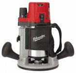
A quick search reveals this Millwakee 2 1/4 hp router looks like it has a really nice smooth bodied motor that could be removed from the router frame and placed into some kind of a sturdy head mount on a CNC router. The 1/2 inch chuck would give it a lot more rigidity and moving to a 1/2 inch mill would speed up machining time a lot since it can remove twice as much material at the same feed rate. Also, a router like this would have much better bearings and cut more accurately. With a 1/2 inch chuck you can also use a much longer mill or router bit which allows you to machine deeper pockets such as a foam mold or something.
Just ideas.
Attachments
Last edited:
I can cut 16mm wide, 3mm deep, at ~1000mm/min with a straight cut router bit.
My DIY CNC is made of string and chewing gum, with a cheap chinese Ozito brand 850w 6.35mm chuck router.
(god I wish inches would just DIE!!!!)
My DIY CNC is made of string and chewing gum, with a cheap chinese Ozito brand 850w 6.35mm chuck router.
(god I wish inches would just DIE!!!!)
😎
ShinOBIWAN went from DIY to MIY.... Manufacture it Yourself

Cant wait to see the speakers being milled. What CAD program are you using? And what are you going to use with the CNC machine?
ShinOBIWAN went from DIY to MIY.... Manufacture it Yourself
Cant wait to see the speakers being milled. What CAD program are you using? And what are you going to use with the CNC machine?
ShinOBIWAN went from DIY to MIY.... Manufacture it Yourself
It's the future! 😀
...A quick search reveals this Millwakee 2 1/4 hp router looks like it has a really nice smooth bodied motor that could be removed from the router frame and placed into some kind of a sturdy head mount on a CNC router...
Hi Hezz - yep, that's basically what I do. I have a 2.25hp Porter Cable 892 router (a motor body like this: Porter Cable Product Details for 2-1/4 HP (Maximum Motor HP) Variable-Speed Replacement Motor for 890 Series Routers - Model # 8902)
(god I wish inches would just DIE!!!!)
I hear ya 🙂
The problem is that in the UK, router bits are sold in imperial, MDF in a mixture of imperial and metric, proper end mills usually in metric, my US made machine is in imperial but I've set it up in metric, and my US made router only has imperial collets. It's a first class PITA!
measurements
what could more simpler than tenths of units
SI should be a world wide application to all measurements
like you said babies are in
LBs, fish the same as with line breaking strain etc
it is darn frustrating to have to apply conversions for the same thing
speedie
what could more simpler than tenths of units
SI should be a world wide application to all measurements
like you said babies are in
LBs, fish the same as with line breaking strain etc
it is darn frustrating to have to apply conversions for the same thing
speedie
Sploo,
All you say sounds about right. However, moving to a proper milling spindle is a very large jump in capacity. But also expense. It is designed to take side trusts and has a lot more horsepower than the little Dremel type router head which is not designed to take significant side trusts. Also, vibration is a big issue with the little Dremel type router heads and the way that it is mounted. I wonder if someone makes a low profile 1.5 - 2 hp router with a 1/2 inch shank capacity that could be adapted to a CNC router like Shin's. That could possibly be a really good low cost upgrade. I doubt if the Dremel type router has any more than 1/8 -1/4 hp.
There's some decent and cheap vfd powered spindles that can be picked up for around £250. These are watercooled 3hp (about the max you'll get on 13A 230v). The dremel looking ones are usually made by Kress and range from around 0.75hp-1.5hp. They have their place but in the grand scheme of things they're a toy compared to the chinese vfd setup.
ShinOBIWAN went from DIY to MIY.... Manufacture it Yourself
Cant wait to see the speakers being milled. What CAD program are you using? And what are you going to use with the CNC machine?
🙂
CAD is Solidworks but I'm still undecided with CAM package. Need to find one that's cheap and does all I want. Tried plenty of demo's so far and have a couple I like but haven't committed money yet. To get started I'm just going to use the freebie software that came with the machine (Vectic VCarve). Ideally I'd eventually like to get SolidCAM XPress as this works beautifully with Solidworks but its expensive for a beginner.
The CNC runs from a PC via the parallel port using the Mach 3 software.
(god I wish inches would just DIE!!!!)
I had a pleasant surprise the other day.
I joined a cnc community not long back and befriended a helpful member on there. I got a chance to chat with him on the phone the other day and the guy is in his prime so I figured he'd prefer if I talked feet and inches rather than mm's. After a couple of minutes he pulled me up about it and said "Look only dress makers and the textiles industry still use inches. Modern day engineering is mm's."
Felt a right prat and serves me right for assuming the oldies prefer to work in inches!
*LOL* Yea, the decent spindles tend to use metric ER collets as far as I understand.
Dunno what you guys are complaining about... everyone knows that 32 and 13/64 of an inch plus two hogsheads and a fathom is larger than a bushel + three shillings and a gnats c*ck 😀
Dunno what you guys are complaining about... everyone knows that 32 and 13/64 of an inch plus two hogsheads and a fathom is larger than a bushel + three shillings and a gnats c*ck 😀

Standard engineering term mate (gnats c*ck) 😉
To convince my other half that it was a real expression, I looked it up on Google. The description I found was something on the lines of:
C*ck, gnat's
Unit of measurement. Significantly smaller than the gnat claims it is.
To convince my other half that it was a real expression, I looked it up on Google. The description I found was something on the lines of:
C*ck, gnat's
Unit of measurement. Significantly smaller than the gnat claims it is.
I can't help but feel this is turning into more of CNC thread than a speaker one but what the hell I'm sure there'll be some audio related stuff in here one day 😛
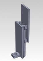
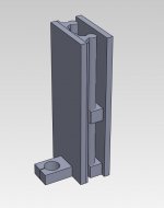
Here's the new Z axis construction that they're doing for the replacement. I've done the drawing in solidworks just to convey the basic idea. Its neat because the higher up the working area the less the Z act as a lever - ideal for alu where you'd raise the stock and take benefit of this.
Here's the new Z axis construction that they're doing for the replacement. I've done the drawing in solidworks just to convey the basic idea. Its neat because the higher up the working area the less the Z act as a lever - ideal for alu where you'd raise the stock and take benefit of this.
Attachments
Standard engineering term mate (gnats c*ck) 😉
To convince my other half that it was a real expression, I looked it up on Google. The description I found was something on the lines of:
And sure enough...
Urban Dictionary: gnat's dick
I'm not sure what's more disturbing, the dictionary entry or my google search to find it.
🙂
CAD is Solidworks but I'm still undecided with CAM package. Need to find one that's cheap and does all I want. Tried plenty of demo's so far and have a couple I like but haven't committed money yet. To get started I'm just going to use the freebie software that came with the machine (Vectic VCarve). Ideally I'd eventually like to get SolidCAM XPress as this works beautifully with Solidworks but its expensive for a beginner.
The CNC runs from a PC via the parallel port using the Mach 3 software.
All of the professional CAM packages are expensive and in the 2000-6000 USD price range. The easiest one to learn I think is called FeatureCAM. It's now part of the company that makes the DelCAM product. MasterCAM is kind of the industry standard in the USA.
That SolidCAM plugin for Solidworks looked pretty nice also the machining module in CATIA is really cool.
There are a couple of less expensive products for the home CNC machinist but they are not as powerful. But fret not.
Most of the CNC programming for speaker cabinets is right angle movement and this kind of CNC programming is very easy to do manually with nothing more than an ASCII text editor and your own brain. For non 90 degree angle movements two simple trig equations are needed to calculate the tool path for 2 1/2D machining. So it's very possible that the cabinets would be roughly 90% right angle cutting paths. With only a couple of non 90 degree angles. There are books you can pick up for a few dollars that show you how to manually do this and in fact it is recommended to learn this anyway as it helps you understand the process of setting up CAM software programming.
For complex surfaces in full 3D there has to be three or more trig calculations done every thousands of an inch or so. You can see how this would get pretty tedious and hence the need for CAM software. However, I think there are some inexpensive CAM packages that can generate the code for a complex surface but that don't have all the other bells and whistles. But everything else is easy to program manually.
Shin, I'm not sure how the controller on your CNC machine is designed. If it is a PC or designed to take code send to it from a PC. There are inexpensive PC CNC utilities that are designed to send the code to a controller through a parallel, serial or USB port. Depending on how much memory is in the controller you can download the whole program or drip it to the controller. The drip method is usually used for large programs with many pages of code. But this only comes up when there is a lot of complex 3D surfaces. For the cabinets parts it is simple 2 1/2 D code that is easier to understand than HTML and can be contained in a ASCII text file of a few kilobytes in size.
Essentially what this means is that you don't need CAM software to program and run your machine until such a time when you want to do complex curved 3D surfaces. You can still do 2 1/2D cuts with manual programming.
Usually with inexpensive CNC machines the PC is used to translate the CNC code (commonly called G-code), into the machine code that sends signals to the stepper motors or servos. What this means is that the PC essentially becomes part of the controller. This makes the CNC controller a lot less expensive since the logic is in the software on the PC and the controller is essentially an amplifier that outputs the PC machine code signals to the motors at a higher voltage and current.
Shin, Here is a link to a company that offers a free basic CAM package that can generate the code for a surface.
http://www.mecsoft.com/freemill.shtml
Basically, if you have a complex surface in Solidworks you can save the part as an STL file and bring it into this package and generate the G code for it. Between saving this G-code output and adding some manual programming you can create a whole program without an expensive CAM package. In fact, I have seen veteran CNC machinists use this method for really complex machining setups.
Hezz
Last edited:
Hey Hezz
Its PC controlled via Mach and parallel port.
This seems to work OK although I might get one of the USB based controller boards eventually so the trajectory planning and so on is off loaded from the PC and it acts as a simple data source rather than a controller. That way I can then use the PC for music/web surfing/CAD in the workshop without fear of interfering with the machining processes.
The PC I use is a Dell desktop with a 3Ghz Core2duo cpu, 2Gb ram and a small 40Gb SSD with XP installed. Very pedestrian compared to more modern offerings but its more than fine for Mach. The annoying thing about Mach is its reliance on the parallel port. Any half decent modern motherboard doesn't bother with this ancient tech anymore so going USB for the controller will allow for a better equipped PC in the workshop which can only be a good thing when it comes to Solidworks as it'll eat whatever resources you throw at it.
Thanks for the tips on the CAM and g-code side of things. I got a copy of Vectric VCarve bundled with the machine and this doesn't look too bad from playing around. It'll do most of what I want but its not suited for 3D and so I will need to upgrade at some point. It'll get me going for now though and it was free.
Tbh I'm keeping an ear to the ground on ebay and hoping to find an older copy of MasterCAM or SolidCAM for little money. They're rare but do pop up every so often. I'm not fussed about an old version as even these are feature rich and the lack of tech support doesn't put me off either.
You don't need to worry about drip feeding or serial stuff with Mach 3.
The PC is the controller and it communicates with the stepper cards (step and direction) via Parallel, or via USB using a Smooth Stepper.
I just use an old 1.6ghz laptop with a parallel port. It works fine. No need to spend $150ish on a Smooth Stepper at this point.
Eventually you will want proper 3D Cam, the router is hobbled without it.
Try this manually...
Attachments

That way I can then use the PC for music/web surfing/CAD in the workshop without fear of interfering with the machining processes.
For the cost of a cheap PC, I'd just have another one (or take a laptop into the garage). No point in risking p*ssing Mach off and making a mess of material/bits/machine. Remember that doing the job of a controller is a hard realtime (Real-time computing - Wikipedia, the free encyclopedia) operation - i.e. a couple of tenths of a second delay to a GUI used by a human isn't a big deal. It is when you're controlling pulses for motors.
The PC you've listed will easily handle Mach though.
Kress has been ditched before even firing it up. Have now gone ahead and ordered one of the chinese 3HP watercooled spindles and vfd.
Budgets are meant to be blown anyway
Budgets are meant to be blown anyway
- Status
- Not open for further replies.
- Home
- Loudspeakers
- Multi-Way
- Apollo Construction Diary