I have built over 60 easy diaphragms which are a doddle in comparison to the apogees. Mine do not require complicated crossovers etc. I have even built 2 full range planar headphones. Which sound wonderful.
I understand. When I first read your post I thought maybe you had come up with an Apogee bass panel alternative.
Thanks for that effort! I have a pair of Scintillas (and other speakers) and they really do sound very, very good albeit a real B*\CH to drive properly.
There are a few amps that can handle these without a sweat. One is the H2O Audio Signature line, of which I have the S250. Henry Ho has been a member of the old Apogee forum for a while and his products are well known within that community.
I have the S250 Signature and it's great with my Apogee Caliper Signatures, Quad ESL-63 and a couple other models. I purchased it with the hopes of using it with a Scintiilla but my plans have changed.
It would be quite easy to fit a different diaphragm to the Apogee family, using mylar and alu foil. You wouldn't need all the tools and the silicon etc. They would be a lot cheaper than the ones you have to buy, about £5 each. If I had one of the apogees stripped, It would be simple to get it up and running and very cheap.But I don't have any broken Apogees. It would be an interesting exercise, as I am running out of interesting jobs, apart from the headphone rebuilds. I also have to rebuild a pair of small 16" x 12" FRP which are noisy, I know what the problem is, now I have heard the consequences, and felt it.You live and learn, which I have over the years, which is part of life when you don't have any qualifications or difficult maths.
If someone could mark all the magnets, holes, diaphragm cutout etc. On some Mylar or whatever (minimum 6 um, although I would prefer 12 um), putting 4 + signs on it corresponding to 4 + signs on the Apogee frame, to set the relative positions of all the markings in black permanent ink. When complete it could be sent to me. I could then stick the alu foil in the correct position. Then return it to you. You could then fit it to the frame, not using any glue as such, so it can be removed as necessary.If anybody thinks this is viable or a good idea, give it a go or not!! It's up to you. Certainly a lot cheaper than buying the diaphragms from sellers of such. Bass panels, although others could work as well ,hopefully! The impedance or resistance of the diaphragm should be stated as well.
Last edited:
I have the S250 Signature and it's great with my Apogee Caliper Signatures, Quad ESL-63 and a couple other models. I purchased it with the hopes of using it with a Scintiilla but my plans have changed.
I have the Duetta Sigs and use a Icepower 1000ASP amp for the bass panels and an Icepower 250ASP amp on the ribbons. There is something real good going on with Apogees and Icepower. All my other speakers (Tympanis, CLS, Acoustats, Sanders, etc) were bested by my Krell KSA50 clone over the Icepowers, but for some odd reason, the Icepowers really make the Apogees sing like no other amp I have tried (and I have tried quite a few).
I do not think the monstrous conventional Class A Type power supply in H20 amps are the reason...it is something inherent to the Icepower design...just my 2 cents.
Henry, I've been tempted to make a 6um mylar ribbon for the Scintilla's, do you think it would have to be corrigated? if not be very simple to make. Where did you find this +4 on the frame, I have a bare one here and can't see anything on it other then the top and bottom alignment marks to set the ribbon centre.
John, I found the S250 the best on the Acoustat 2+2's., best amp on the Scins is my modified Bryston 6B mono blocks, then the S250, Krell KSA250 third. Al
John, I found the S250 the best on the Acoustat 2+2's., best amp on the Scins is my modified Bryston 6B mono blocks, then the S250, Krell KSA250 third. Al
1. Scintilla alignment: I thought it was the same for all the basic models, as shown in the Apogee repair video?
2. corrugation: I would not avoid this, as it adds to strength and damping. All you need is a wide enough roller and just run it on the panel while laying it on some soft foam - to give it a deep enough corrugation. Now, finding one may be a challenge but there should be some sort of machinery that uses this type of roller. Of course, best is to have two machined and run the panel through them.
3. Getting back to the supplies, what Kapton, foil and glue should we use? I thought I'd try and make a mini-Scintilla when my Cal Sigs die, including a 1-ohm panel and maybe a MRT arrangement like the Scintilla's. Doable?
Art, I suspect the magnetic field of the cal's would be to weak for that arrangement, The corrugation is a pita, easy to split the foil from uneven displacement pressure doing few traces, 3 almost max at a time. I'm going to get a big vertical bridgeport mill to machine the ribbon circuit into steel templates, after that the foil will be a piece a cake, all exact, and can do double side as well such as stage and studio array. I use deluted 3M77 and use a small spray gun and mist the foil, then roll the kapton down. Whats the size of magnets used on the bass section of the Caliper?. whats their vertical row centre? Curious if Apogee made all the circuits based on the same row centre. Al
Henry, I've been tempted to make a 6um mylar ribbon for the Scintilla's, do you think it would have to be corrigated? if not be very simple to make. Where did you find this +4 on the frame, I have a bare one here and can't see anything on it other then the top and bottom alignment marks to set the ribbon centre.
John, I found the S250 the best on the Acoustat 2+2's., best amp on the Scins is my modified Bryston 6B mono blocks, then the S250, Krell KSA250 third. Al
There are no + signs on the Apogee, this is something I use when I build my diaphragms (over 60). This helps to align my diaphragms, when I fix them in position. I only build full range diaphragms, and do not corrugate any of them!. You could use the alignment marks if convenient, my + marks align vertically and horizontally. Which is more helpful when the diaphragm is very wide and long. It makes it easier for me, equivalent to the alignment marks on Apogees and others.
Henry, Whats the centre distance of the magnet rows on the full range? How does the flat panel sound compare to the corrugated panel? Is there much bass loss and resonance issues? What you using> mylar or kapton? are you tensioning the ribbon using the original system or using a fixed method? Is your DS depth still as original? picking your brain here cause I'm sick of my failure rates. Al
CONFUSION REIGNS.
I'm afraid you have got the wrong end of the stick. I have no APOGEES whatsoever, I was referring to my own full range planar builds, which I have built over 60 over the last 20 or more years. I was referring to someone making a mylar copy of an APOGEE layout, and sending it to me so I can make one of my diaphragms to fit the relevant diaphragm cutout. Using my method of diaphragm build. I have had no problems with the flat panels using mylar and alu tape. When I tension the diaphragm I use my fingers to pull the mylar into position and get rid of the creases etc. Using a wood frame and screws. The APOGEES already have a frame round the cutout. You could use this with my diaphragm. The copy if you send one must be accurate and includes all the relevant positions marked out in permanent pen.
I'm afraid you have got the wrong end of the stick. I have no APOGEES whatsoever, I was referring to my own full range planar builds, which I have built over 60 over the last 20 or more years. I was referring to someone making a mylar copy of an APOGEE layout, and sending it to me so I can make one of my diaphragms to fit the relevant diaphragm cutout. Using my method of diaphragm build. I have had no problems with the flat panels using mylar and alu tape. When I tension the diaphragm I use my fingers to pull the mylar into position and get rid of the creases etc. Using a wood frame and screws. The APOGEES already have a frame round the cutout. You could use this with my diaphragm. The copy if you send one must be accurate and includes all the relevant positions marked out in permanent pen.
Attachments
-
 SAM_0146.JPG422.6 KB · Views: 436
 -
 SAM_0230.JPG345.9 KB · Views: 150
 -
 SAM_0214.JPG374.2 KB · Views: 184
 -
 SAM_0205.JPG425.2 KB · Views: 189
 -
 SAM_0203.JPG430.7 KB · Views: 149
 -
 SAM_0201.JPG421.1 KB · Views: 135
 -
 SAM_0197.JPG428.2 KB · Views: 374
 -
 SAM_0168.JPG761.2 KB · Views: 403
 -
 SAM_0167.JPG814.8 KB · Views: 410
 -
 SAM_0162.JPG680.5 KB · Views: 435
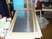
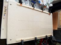
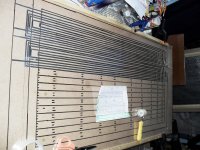
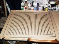
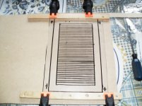
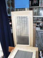
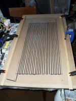
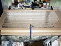
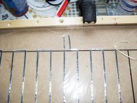
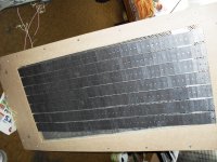
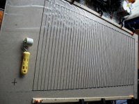
diaphragm markings before putting tape on using + markings
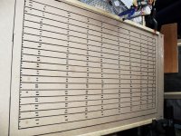
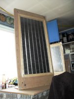
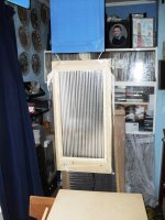
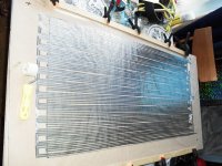
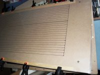
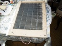
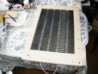
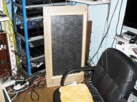
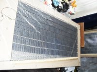
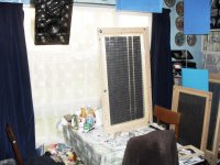
some more pics of layouts etc. Giving an idea of what I mean about marking the diaphragms so I can put the alu tape in the right position, accuracy is all important and you can see the +'s I use on some of the diaphragms.
some more pics of layouts etc. Giving an idea of what I mean about marking the diaphragms so I can put the alu tape in the right position, accuracy is all important and you can see the +'s I use on some of the diaphragms.
Attachments
-
 SAM_0332.JPG357 KB · Views: 131
 -
 SAM_0317.JPG425.9 KB · Views: 145
 -
 SAM_0312.JPG353.3 KB · Views: 137
 -
 SAM_0305.JPG395.3 KB · Views: 128
 -
 SAM_0300.JPG411.6 KB · Views: 136
 -
 SAM_0298.JPG404.5 KB · Views: 121
 -
 SAM_0297.JPG450.6 KB · Views: 119
 -
 SAM_0290.JPG438.8 KB · Views: 130
 -
 SAM_0266.JPG437.4 KB · Views: 116
 -
 SAM_0265.JPG376.3 KB · Views: 123
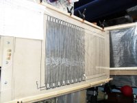
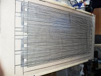
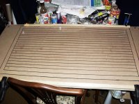
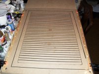
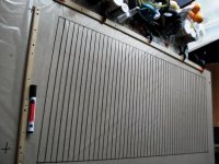
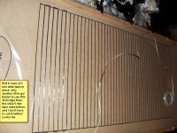
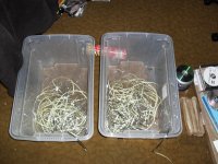
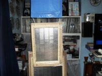
some more pics.
Some more pics of my own designs of full range planars. I hope these pics help to explain my offer.
Some more pics of my own designs of full range planars. I hope these pics help to explain my offer.
Attachments
-
 SAM_0436.JPG425.1 KB · Views: 112
 -
 SAM_0356.JPG390.5 KB · Views: 104
 -
 SAM_0355.JPG438 KB · Views: 105
 -
 SAM_0354.JPG381.2 KB · Views: 101
 -
 SAM_0353.JPG415.1 KB · Views: 87
 -
 SAM_0344.JPG458.4 KB · Views: 93
 -
 SAM_0339.JPG390.3 KB · Views: 94
 -
 SAM_0337.JPG415.3 KB · Views: 105
 -
 SAM_0336.JPG404.1 KB · Views: 123
 -
 SAM_0444.JPG390.3 KB · Views: 115
...picking your brain here cause I'm sick of my failure rates. Al
What do you mean, Al? Failing corrugations or materials in general?
Since we know the geometry of Apogee panels, seems to me the remaining issue is choice of materials. Then try it without corrugations and see how it goes.
I don't mind sticking with Kapton as in the original design as Apogee knew what they were doing. I fear stretching mylar would impact the integrity of the mylar/foil bond. As long as I can buy the supplies I'll give it a try.
However, since Henry has apparently had success with this design it certainly is worth the effort - but not for me at the moment as my Apogees are working fine. I wish I had an extra bad pair so I can tinker with them.
Art, by failure I mean the time wasted on cutting the foil circuit and having it tear and start all over again, exacto knives and round cutters are not the answer, that's why I want to machine a template, be perfect everytime, the other thing now is getting hold of kapton, Dupont won't set up for a small amount.I'm out of kapton myself, got 3 panels out of a 100' roll, should have done 15 miniumn, thats why I looking at mylar now. Al
...I mean the time wasted on cutting the foil circuit and having it tear and start all over again, exacto knives and round cutters are not the answer...
Have you considered etching the unwanted aluminum away after it's bonded to Kapton? I did a quick search for lithographic techniques that started to lead me in the right direction. With some additional research there ought to be an answer out there somewhere. It also appears that Kapton films are available with an aluminum coating, either laminated or vapor deposited. I didn't check on available widths and thicknesses yet though. Just another avenue to consider. I'd go with Kapton because it is dimensionally stable and far more heat resistant than Mylar.
Brian, I gave that an attempt with acid in a pen plotter, but the trace width varied to much and gave up, a waste of more kapton 🙂 . Let us know what you find out in your research, I wonder if 1 mil kapton would be to thick. I think the Scintilla used 1/2 mil if I remember correctly. Al
3mil circuit!
What are you referring to? I have used mylar since I started using neos, When I first started I used plastic rubbish bags, decorators stair plastic, which went very brittle after time. It was the aluminium foil which held it together, so good glue, from CPC 9 mm wide. Which I cut in half twice down to 2.25 mm by hand, but I use the 3 mm tape now which is a lot easier and is very cheap.I have about a hundred yards of 23 um mylar C to use up. So I use this at the moment with the 3 mm tape. Depending on the width of magnets and the strength used you can either use the normal layout or you can use the epsilon variety of layout. This uses a hell lot of tape, and requires patience and a good healthy back. Still manage it at 75 years old, so can't be all that difficult!! It is best to use a sufficient amount of tape so you can set the impedance of the diaphragm to match up with your amp. All my speakers can be run by any amp valve or otherwise, so no problem in that respect.Setting the impedance match is not easy, On some of my diaphragms I have used over 50 meters of 3 mm tape, and had to split it in half and parallel the 2 halves to get the correct impedance. You live and learn sometimes the hard way. I am not very good at writing things down and my memory is not so good at my age. Still it makes life interesting especially at my age.
Henry, whats the resistance on your 3mil circuit, must almost be a dead short. Al
What are you referring to? I have used mylar since I started using neos, When I first started I used plastic rubbish bags, decorators stair plastic, which went very brittle after time. It was the aluminium foil which held it together, so good glue, from CPC 9 mm wide. Which I cut in half twice down to 2.25 mm by hand, but I use the 3 mm tape now which is a lot easier and is very cheap.I have about a hundred yards of 23 um mylar C to use up. So I use this at the moment with the 3 mm tape. Depending on the width of magnets and the strength used you can either use the normal layout or you can use the epsilon variety of layout. This uses a hell lot of tape, and requires patience and a good healthy back. Still manage it at 75 years old, so can't be all that difficult!! It is best to use a sufficient amount of tape so you can set the impedance of the diaphragm to match up with your amp. All my speakers can be run by any amp valve or otherwise, so no problem in that respect.Setting the impedance match is not easy, On some of my diaphragms I have used over 50 meters of 3 mm tape, and had to split it in half and parallel the 2 halves to get the correct impedance. You live and learn sometimes the hard way. I am not very good at writing things down and my memory is not so good at my age. Still it makes life interesting especially at my age.
For corrugating, how about using some "pinion rod":
https://sdp-si.com/eStore/Catalog/Group/438
Welcome to Boston Gear
Pinion Rod
Also, spur gears like this:
Spur Gears | Pinion Shaft |Steel Spur Gear Stock | Grob, Inc.
I haven't investigated pricing but the rods are cheaper, as they are extruded not machined. Of course, knowing which specification is needed will be difficult to determine and you can't do trial and error as these are not cheap.
So, I don't know if this helps any...
- Home
- Loudspeakers
- Planars & Exotics
- Apogee Speakers Construction