Retensioning won't do it.
Beside the crack, the foil is very uneven, plus I suppose you've got the buzz.
The foil is uneven because it's so loose, which tensioning would fix. I really don't want to spend $1500 repairing a speaker that sells for one third that much.
Why not? The Kapton backing is in good shape. Fixing breaks in the foil is easy. I can't find any helpful videos or even a foil schematic on line, which would help quite a bit.
Last edited:
I too don't know about a pic that shows the path on the foil.
Fixing breaks is easy? Depends on where the break is.
Easy only, if the break is not, where the foil moves.
There you could use stripes of thin material, that conducts (copperfoil or similar)
But if the crack is, where the foil hangs free, what will you use?
It must be durable, conductive, flexible, lightwight, glueable,....
Not so trivial, imo.
I too don't know about a pic that shows the path on the foil.
Fixing breaks is easy? Depends on where the break is.
Easy only, if the break is not, where the foil moves.
There you could use stripes of thin material, that conducts (copperfoil or similar)
But if the crack is, where the foil hangs free, what will you use?
It must be durable, conductive, flexible, lightwight, glueable,....
Not so trivial, imo.
I don't have any breaks where the foil moves, just under the frame board. I seems odd that there's no schematic for the foil after all these years.
I don't have any breaks where the foil moves, just under the frame board. I seems odd that there's no schematic for the foil after all these years.
There is a schematic of the foil on page 18 in the document link in post 105.
I have had to repair mine once before here,
http://www.diyaudio.com/forums/planars-exotics/196631-apogee-speakers-construction.html#post3409337
And now I find I have to do it again in a different spot and on the other side as well as they were fused open underneath the glued supports!! 🙁
I had to use an ohm meter to find the right spot.
jer 🙂
Last edited:
I have Been Working on the Duetta Sg Buzz.....
I have found that with the Stages i can Make Buzz on the bass panels... by have the feet ajustment off.... on one side are the other....the floor is never flat!.....An the MDF board flaxs ...an pull the magntes in or out away from the foil...this makes Buzz!
So now i have been working on the Duettas Feet not as eze as the stages No ajust ment......How minny have stikes??....An help to move them around.
An have found that i can get 99% of the buzz out with the feet ajustment....one side are the other being moved up or down.. Front to back....
.This will get ret of a lot of buzz in any of the Apogees even after or like me befor... your fix .....an the bass gets even better ...gofig...
lot of work to done on the Apogees still to get the best sound you can...Thanks for any an all info on Apogees ribbons
There is a schematic of the foil on page 18 in the document link in post 105.
I have had to repair mine once before here,
http://www.diyaudio.com/forums/planars-exotics/196631-apogee-speakers-construction.html#post3409337
And now I find I have to do it again in a different spot and on the other side as well as they were fused open underneath the glued supports!! 🙁
I had to use an ohm meter to find the right spot.
jer 🙂
That "schematic" doesn't show the actual circuit.
Maybe this will help you,
Do It Yourself - Ribbon Speakers - Project: La Folia magnetostatic by Mogens Gallardo
I have seen a better diagram but I don't have the link at the moment.
http://www.magnetostatic.com/
http://www.magnetostatic.com/design.html
jer🙂
Do It Yourself - Ribbon Speakers - Project: La Folia magnetostatic by Mogens Gallardo
I have seen a better diagram but I don't have the link at the moment.
http://www.magnetostatic.com/
http://www.magnetostatic.com/design.html
jer🙂
Last edited:
That "schematic" doesn't show the actual circuit.
I assume you're not talking about the crossover "schematics", but rather the cut pattern in the woofer membrane?
There is little information/photographs of this scheme since it requires removing the side clamps to visualize the circuitous route the signal takes. There used to be some photographs on the Apogee site, but those seem to have been taken down or "lost." 🙂
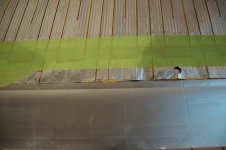
Your speakers appear to have damage on the bottom trace (one of your photo's is very blurry) and the previous owner has bypassed the break with a copper shorting piece that disabled a small portion of the woofer. (A fairly effective, simple field repair it seems.)
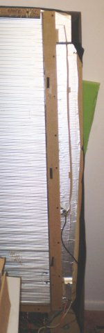
Your speakers also show what appears to be a loss of tension in one area of the membrane. (The "diagonal" creases in the membrane.)
unfortunately, it appears your speakers are not usable at this time, but if you really have the DIY spirit then have some fun and see if you can re-tension the membrane without doing damage. The appropriate frequencies for each area of the membrane are in the speaker test procedure document.
Cheers,
Dave.
I assume you're not talking about the crossover "schematics", but rather the cut pattern in the woofer membrane?
There is little information/photographs of this scheme since it requires removing the side clamps to visualize the circuitous route the signal takes. There used to be some photographs on the Apogee site, but those seem to have been taken down or "lost." 🙂
Your speakers appear to have damage on the bottom trace (one of your photo's is very blurry) and the previous owner has bypassed the break with a copper shorting piece that disabled a small portion of the woofer. (A fairly effective, simple field repair it seems.)
Your speakers also show what appears to be a loss of tension in one area of the membrane. (The "diagonal" creases in the membrane.)
unfortunately, it appears your speakers are not usable at this time, but if you really have the DIY spirit then have some fun and see if you can re-tension the membrane without doing damage. The appropriate frequencies for each area of the membrane are in the speaker test procedure document.
Cheers,
Dave.
Thanks for the encouragement.
The copper shorting strips in one of your photos is completely bypassing one of two voice coils on the bass panel.
If you take them off you may find that a section is open and is probably why they are there.
The LaFoiia Project V.C. is exactly the same.
On my panel, the narrow width foils on the top and bottom going in to the diaphragm is one V.C. and the other two wide ones is the other V.C..
They are in series by the wide outside strip that runs continuously from top to bottom.
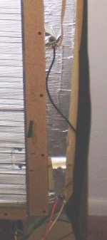
The black wire is ground and is connecting to the bottom tab on the top.
The orange and white positive wires are the same connecting to the bottom tab on the bottom.
jer 🙂
If you take them off you may find that a section is open and is probably why they are there.
The LaFoiia Project V.C. is exactly the same.
On my panel, the narrow width foils on the top and bottom going in to the diaphragm is one V.C. and the other two wide ones is the other V.C..
They are in series by the wide outside strip that runs continuously from top to bottom.
The black wire is ground and is connecting to the bottom tab on the top.
The orange and white positive wires are the same connecting to the bottom tab on the bottom.
jer 🙂
Attachments
The copper shorting strips in one of your photos is completely bypassing one of two voice coils on the bass panel.
If you take them off you may find that a section is open and is probably why they are there.
jer 🙂
With the jumper installed he's measuring 3.1 ohms DC. That's right in the nominal range for the Caliper woofer. That would indicate the majority of the woofer transducer is active and clearly not bypassing (completely) one of the voice coils. If they're in series and he jumpered one of them out he should measure approximately 1.5 ohms, no?
Some further detective work to be done here I guess.
Cheers,
Dave.
Last edited:
Mine are Duette's so I am not sure how much of a difference there is between the two.
Here is the post of when I measured the D.C. resistance of my bass panels,
http://www.diyaudio.com/forums/planars-exotics/196631-apogee-speakers-construction.html#post3409337
Sorry if I have created any confusion's.
Cheers!!
jer 🙂
P.S. I didn't see the picture of the bottom set of jumpers until now.
If they were Duette's than they would appear to be in parallel.
And by judging that if the pattern is the same then they very well may be in parallel as well.
Again I only have experience with the Duette's.
Last edited:
From Daveys Apogee tuning pdf posted earlier, the Caliper bass panel DC resistance is 3.1 to 3.4 ohms. I agree with Davey - I do not see how you can bypass a coil section and still have the right dc resistance.
Is that your Calipers on Agon now? For your asking price I would take them myself for a refurb...too bad I am in Chicago and may be too expensive to ship.
EDIT - yes, they are. If your willing to ship to 60585 I may be interested in them. Although I have had bad luck so far - got a pair of Caliper Tweeters delivered totally destroyed by UPS. Magnets completely broken off the rails...
Trade for an ICEPower amp? I also have quite a few ICEPower modules too (250ASP, 250A, etc). I need another project like I need a hole in my head...
Last edited:
Oh hell, here is what I would do... if your up for it, do the following. Be very careful, as you should have no issues selling them as is... and look through the posting I had showing all the pics.
The sides, top and bottom wooden clamps... my guess is that they are all loose, but only the top and bottom clamps should only be slightly loose (the top and bottom clamps are supposed to be snug, but not tight, while the sides should be relatively tight. - got this info from Graz). If your side clamps are not loose, do not proceed...
With the top and bottom clamps removed (DO NOT ATTEMPT TO TAKE OFF THE SIDE CLAMPS - THE DIAPHRAGM MAY BE GLUED TO THE SIDE CLAMPS), you will see the top ribbon/kapton diaphragm on both sides as they go underneath the side clamps.
What I see happening in the side wooden clams are way too loose (you can check - are they loose / do they wiggle? They should not). Apparently the clamps are loose, and diaphragm is sagging. From my previous link (german) you will see pics of what screws are used to tighten the clamps,and which screws are to tension the moveable clamp. At this point, don't screw with the tension screws. See if you can pull taught the diaphram under loose clamps, and then tighten the clamps to hold them in.
Pull up on the diaphram near the side clamps.the wrinkles should flatten. You can further loosen the side clamp screws, but be gentle on pulling up...Do the same on the other side. Be careful, you do not want to make more tears in the diaphragm. Once wrinkles are flattened, tighten the side clamps. Make sure they are relatively tight, so the diaphram cannot droop. Now put on the top and bottom clamp. These are to be slightly loose, and according to Graz, keeps the diaphragm from "bagging" on the bottom. It is the side clamps that hold the diaphragm in place.
Post back...but see those German posted pics first!!
Last thing, check the DC resistance - should be 3.1 to 3.4 ohms...be advised that you could do more damage pulling up the diaphragm, resulting in weird DC resistance...
Last edited:
In all of the pictures that I could find the Caliper's appear to be just physically a little shorter version of the Duette's.
If the sources of the pictures are correct as per model they have the very same construction.
In none of the pictures have I found the copper shorting strips and the two sections are tied in series.
The shorting bars that are described in the manual are the ones referring to the binding post connections.
The nominal impedance of 3 ohms that is stated is an overall figure and it is very vague as to how they came up with this figure.
It could have been stated as such for when one goes to select their amplifier as a minimum to be stable condition.
As the Ribbon tweeter does measure about 3 ohms of D.C. resistance and typically is in parallel with the bass panel in a stock configuration using one amplifier
DIS-Magnetostaten :: exclusive Lautsprechermanufaktur
°allabout-hifi°:Galerie: Bild anklicken, um das Fenster zu schließen!
http://blog-imgs-31-origin.fc2.com/g/o/g/gogowildcherry/090324-2.jpg
Apogee Thomas Schick
all of these were found here,
apogee caliper - Google Search
jer 🙂
I have those very same sags but only at the bottom 12" of both of my the panels.
I will be moving my recording equipment out next week to a new location for a recording job and this will give me the room to lay one down and take a closer look at it.
jer 🙂
I will be moving my recording equipment out next week to a new location for a recording job and this will give me the room to lay one down and take a closer look at it.
jer 🙂
Looking at the above photo with jumper, looks like the break may be on other side of that trace,perhaps under foam area or clamp area itself
Looking at the above photo with jumper, looks like the break may be on other side of that trace,perhaps under foam area or clamp area itself
That is correct, my Canadian friend. I have removed the original jumper and transferred it to the opposite side, which is where the break occurred, under the the right clamp, as you suspected. I must have a few more of these, as a few bands are still getting no current.
Still no proper schematic of the bass panel?
- Home
- Loudspeakers
- Planars & Exotics
- Apogee Speakers Construction