Hello All,
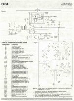
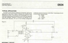
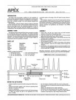
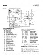
Before going any further let me add a little clarification. The evaluation kit I used is quite old and different from what is available today. Attached are copies of information from the data sheet that came with the kit I used (may help explain what Apex thought about R8, R10 and C10, but I am at a loss to explain my thinking at the time). The circuit shown in the schematic is what I used as a guide for my build. Also, the data sheet that came with the PA05 is different from current versions, in that, it does not show an equivalent schematic. So, should I assume that internal protection diodes were or were not used at that time?
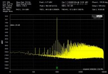
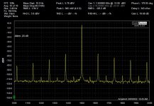
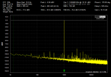
Moving on to actual testing. As suggested by BSST, I lifted the C10 lead going to R8, thus removing C10 and R10 from the circuit, and I tacked a short across R8. The attached distortion spectrum was taken at 1KHz, 1 watt in to a 4 ohm load. As compared to the previous spectrum, the noise floor between 1 and 10KHz is down quite a bit, but still, lots of distortion.
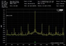
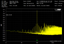
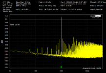
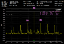
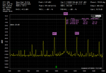
Next, I looked for intermodulation distortion, as suggested by BSST. The final two attachments show the distortion spectrum with an expanded scale for two different frequencies. It looks like I do have IM distortion at 120Hz.
I will start looking for a ground problem somewhere.
techtool, I looked for your project, but could not find it. I had a lot of trouble even finding the photo gallery!
Thanks for all the help.
Cheers,
ceulrich
Before going any further let me add a little clarification. The evaluation kit I used is quite old and different from what is available today. Attached are copies of information from the data sheet that came with the kit I used (may help explain what Apex thought about R8, R10 and C10, but I am at a loss to explain my thinking at the time). The circuit shown in the schematic is what I used as a guide for my build. Also, the data sheet that came with the PA05 is different from current versions, in that, it does not show an equivalent schematic. So, should I assume that internal protection diodes were or were not used at that time?
Moving on to actual testing. As suggested by BSST, I lifted the C10 lead going to R8, thus removing C10 and R10 from the circuit, and I tacked a short across R8. The attached distortion spectrum was taken at 1KHz, 1 watt in to a 4 ohm load. As compared to the previous spectrum, the noise floor between 1 and 10KHz is down quite a bit, but still, lots of distortion.
Next, I looked for intermodulation distortion, as suggested by BSST. The final two attachments show the distortion spectrum with an expanded scale for two different frequencies. It looks like I do have IM distortion at 120Hz.
I will start looking for a ground problem somewhere.
techtool, I looked for your project, but could not find it. I had a lot of trouble even finding the photo gallery!
Thanks for all the help.
Cheers,
ceulrich
Attachments
-
 1 EK04 Original Data Sheet 1.jpg422.3 KB · Views: 213
 -
 2 Apex Application Schematic.jpg70.6 KB · Views: 215
 -
 3 PA05 Low Power Amp -03-29-22.jpg154.9 KB · Views: 135
 -
 4 PA05 Low Power Amp - Left - 1 KHz - 03-30-22.jpg175.2 KB · Views: 122
 -
 5 PA05 Low Power Amp - Left - 1.5 KHz - 03-30-22.jpg173.6 KB · Views: 171
Hi Ceulrich,
If you get stuck on the hum hunt, I've had a thought.
Aside from the blocking cap at the input, your amp is DC coupled and you might use that fact to your testing advantage. Drive the input pot with a DC voltage (might be as simple one or two 1.5V batteries nestled inside chassis) so that you can drive the output to any convenient DC voltage. Any hum present in the output is problematic. You can vary output loading from open to down to a few ohms. I'm guessing you'll see hum amplitude rise as the load gets heavier. Also look for hum in the regulators. I believe not having to suppress a 1KHz test signal will simplify troubleshooting.
Good luck!
Hi,techtool, I looked for your project, but could not find it. I had a lot of trouble even finding the photo gallery!
The Chip Amp Photo gallery is the first item in the Chip Amp Forum. My amps were built with the Apex PA07 and PA12 chips which are a little different than the PA05. I didn't post any schematics or distortion measurements... just construction photos, so maybe not much help for your issues. Last post is #3401 on page 171. I don't have any hum/noise problems but, on the other hand, I've never listened to the amp output directly with headphones either. I use both amps daily as my main listening systems and like the sound a lot. Best of success with your project. Thanks.
David
Completely agree. One way to look at this "noise gain" is to view the circuit as a 20:1 attenuator (10k R7 and 500R R10) merged into a x200 amp stage (100k R1 and 500R R10), which is going to be very noisy as a consequence, and throw away lots of open-loop gain (so increasing distortion). The capacitor limits the effect to higher frequencies (the roll off is at 3.7kHz), but that's enough for considerable hiss to be generated and for the distortion to be rising rapidly above 300Hz or so.I'm baffled by the presence of C10 and R10. Sometimes such a network is employed to address instability (oscillation), but nothing I can spot in the Apex data sheet suggests it is necessary. The signal path gain is 10 (20 dB), but R10 introduces "noise gain" of 200 (46 dB), which might be responsible for the hiss you've noted. Its presence will also degrade distortion performance. I would suggest removing R10 and looking for noise (and perhaps THD) improvement. Be sure to use a dummy load and look for oscillation.
techtool, thanks for pointing me in the right direction, never dawned on me that there would be photo gallery for each forum, just a little dense I guess. That’s a really fantastic looking project! Thanks for sharing.
Cheers,
ceulrich
Cheers,
ceulrich
Hello All,
In the past when I have been working on a grounding problem, I compare single-ended measurements to some differential measurements. The differential measurement will eliminate any common mode 60Hz related noise, and gives me a measure of amplifier only distortion.
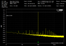
For the PA05 amplifier, the differential distortion spectrum is essentially the same as the single-ended spectrum (see attachments 1 and 2, 4 ohm load at 1 watt). The load needs to be reduced to around 0.3 watt before the amplifier’s distortion is not buried in the 60Hz related noise (attachment 3). Usually I assume that a 120Hz hum is a grounding problem, but I am not so sure in this case. I would be interested to learn what others think.
Cheers,
ceulrich
In the past when I have been working on a grounding problem, I compare single-ended measurements to some differential measurements. The differential measurement will eliminate any common mode 60Hz related noise, and gives me a measure of amplifier only distortion.
For the PA05 amplifier, the differential distortion spectrum is essentially the same as the single-ended spectrum (see attachments 1 and 2, 4 ohm load at 1 watt). The load needs to be reduced to around 0.3 watt before the amplifier’s distortion is not buried in the 60Hz related noise (attachment 3). Usually I assume that a 120Hz hum is a grounding problem, but I am not so sure in this case. I would be interested to learn what others think.
Cheers,
ceulrich
Attachments
Hi ceulrich,
Are you sure the first two pics aren't the onset of instrumentation overload? To test this notion, will your setup allow you to revisit pic 3 test levels and then increase gain between amp under test and A/D input? If overload is is a culprit, increased gain of about 6dB will recreate the pic 1 and 2 forest of distortion.
Hum may be something other than simple grounding. Can you show layout of regulators and the connections of modules?
Hello BSST
Regarding instrumentation overload, the QA401 has a maximum input of 20Vrms and +/- 5VDC. For pics 1 and 2, in the previous post, the peak signal level was 1.98Vrms. The amplifier’s DC offset was previously measured at less than 1mV. So, I don’t think instrumentation overload was the problem. Implementing the testing you suggest would be difficult since the PA05 output goes directly to the QA401 input, with no way to adjust gain at that point. However, the QA401 does have a built in 20dB input attenuator. So, I duplicated the conditions for Pic 3 in the previous post, collected a spectrum, then tuned OFF the attenuator, and collected a second spectrum (attachments 1 and 2). The spectrums are essentially identical, which I interpret as indication that ADC overload is not an issue.
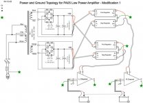
Attachment 3 shows a diagram of the power and grounding topology for the PA05 amplifier. Note that both the positive and negative rails of the regulator are based around LM337 negative regulators.
Any additional comments or suggestions are appreciated.
Cheers,
ceulrich
Regarding instrumentation overload, the QA401 has a maximum input of 20Vrms and +/- 5VDC. For pics 1 and 2, in the previous post, the peak signal level was 1.98Vrms. The amplifier’s DC offset was previously measured at less than 1mV. So, I don’t think instrumentation overload was the problem. Implementing the testing you suggest would be difficult since the PA05 output goes directly to the QA401 input, with no way to adjust gain at that point. However, the QA401 does have a built in 20dB input attenuator. So, I duplicated the conditions for Pic 3 in the previous post, collected a spectrum, then tuned OFF the attenuator, and collected a second spectrum (attachments 1 and 2). The spectrums are essentially identical, which I interpret as indication that ADC overload is not an issue.
Attachment 3 shows a diagram of the power and grounding topology for the PA05 amplifier. Note that both the positive and negative rails of the regulator are based around LM337 negative regulators.
Any additional comments or suggestions are appreciated.
Cheers,
ceulrich
Attachments


Hi ceulrich,
I'm sorry instrumentation overload isn't the problem. I was hoping for a simple solution...
I note in the two spectrums above that the hum appears to be linear addition/supperposition of 1kHz and harmonics of 60 Hz, i.e. 16*60Hz=960Hz and 17*60Hz=1020Hz. At higher power, (e.g. post 27) the spurious appear to be harmonics of 120Hz, but I can't tell from the limited photo resolution if they are 120Hz harmonics or/and if they are IM products of 120HZ and the 1kHz test signal. Can you sort out the possibilities? Try trimming the test frequency so that it's near one of the nearby harmonics; if it's linear addition, the spurs will maintain fixed frequency positions, but if they're IM they will "track" the test frequency with contstant 120Hz offest. This distinction may a be clue.
I see you're from "mid Ohio." Post college, I spent my entire career in Cincinnati. 🙂
Steve
Thanks for the data above, especially the third pic illustrating interconnection of the sub-circuits.
Would you post the remaining data sheets from the original eval board? I'd like to scrutinize them relative to current practice, which I think is probably EK45?
https://www.apexanalog.com/resources/products/ek45u.pdf
I'm afraid I have a very skeptical view of the grounding scheme. If I interpret correctly, the ground for each amplifier flows through a single connection (near the input with a nearby triangle ground symbol) and flows to volume pot and to star ground. My concern is that the ground currents that flow are not neccessarily low distortion replicas of the input signal, and that wiring resistance will allow non-linear currents to sum into the signal path. Note that any dynamic asymmetries in the B+/B- amp currents and their bypass caps/regulators have to flow though this ground wire. NOT good, IMHO!
My instinct is that a twisted triple should should connect B+, B-, and regulator common to the amplifier module. A carefully routed trace (i.e. no supply related currents flowing in this trace) should then pick up the amp module's non-inverting input and lead to volume pot, input jack, and signal ground. And then there's the other channel to worry about.
I'm no expert in these dilemmas. I hope other members will offer input.
Steve, thanks for the additional suggestions. Cincinnati, born and raised there, great town.
Let’s see if I implemented your directions correctly. Pic 1 shows an expanded scale distortion spectrum for a 1 KHz test signal with “spurs” at 880.37 Hz and 1.1206 KHz.
For Pic 2 the test signal was 1.1 KHz resulting in “spurs” at 979.98 Hz and 1.2202 KHz.
Am I correct in thinking that this implies IM distortion?
I will study your comments regarding grounding and report back shortly.
Cheers,
ceulrich
Attachments
Yes, I believe IM is implied.
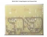
Would you also provide layout detail on the regulator PCBs? Somehow rectified hum is finding its way into the signal path.
Would you also provide layout detail on the regulator PCBs? Somehow rectified hum is finding its way into the signal path.
Last edited:
Steve, attachments 1-5 is the full data sheet for the Apex PA04 Evaluation Kit. Sorry for all the pages, the site would not accept a PDF. Moderator, if there is another way to do this, please advise.
Thanks again for your continued interest and suggestions.
I share your doubts about the grounding topology. What my thinking was at the time is lost in the mists of time, but prior to bringing this to the Forum, I spent a few weeks reading current grounding ideas and changing various ground points. For example: A - removed the connection between the safety ground and the star ground, B - connected the input ground to the potentiometer ground and then going to the star ground, C – running a wire from R15 to the star ground (see clarification below), D - removed power to the channel not under test to eliminate those grounds. Of course, no improvement resulted from any of these changes.
Regarding twisted triple power wiring, note that the actual PA05 does not have a ground pin, and the PCB does not have an identified connection point for a PS ground. So, where does one actually tie the circuit to ground? At the time I built the amp, I chose to use the input ground, which I tied to the PCB ground plane at R15, see attachment 2. Back in post #3 jasonhanjk suggested that “the input ground to the amp board should connect from the star ground.” I have not tried that yet because some other topologies I have read about take the input connector ground to the amplifier ground input and then to the star ground through a “hum breaking resistor.” But it is on my list to try if I have to completely rewire the grounding topology.
When I do that rewire, I thought of starting with the topology shown in attachment 3. Any and all comments are appreciated.
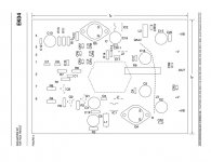
Attachment 4 shows the regulator PCB, by today’s standards, rather crude. This was originally designed for use with preamps with current needs on the order of 100mA. Since I had dozens of these available at the time, and the data sheet indicated I could get 1-2 amps out of them, I went ahead and used them.
Cheers,
ceulrich
Thanks again for your continued interest and suggestions.
I share your doubts about the grounding topology. What my thinking was at the time is lost in the mists of time, but prior to bringing this to the Forum, I spent a few weeks reading current grounding ideas and changing various ground points. For example: A - removed the connection between the safety ground and the star ground, B - connected the input ground to the potentiometer ground and then going to the star ground, C – running a wire from R15 to the star ground (see clarification below), D - removed power to the channel not under test to eliminate those grounds. Of course, no improvement resulted from any of these changes.
Regarding twisted triple power wiring, note that the actual PA05 does not have a ground pin, and the PCB does not have an identified connection point for a PS ground. So, where does one actually tie the circuit to ground? At the time I built the amp, I chose to use the input ground, which I tied to the PCB ground plane at R15, see attachment 2. Back in post #3 jasonhanjk suggested that “the input ground to the amp board should connect from the star ground.” I have not tried that yet because some other topologies I have read about take the input connector ground to the amplifier ground input and then to the star ground through a “hum breaking resistor.” But it is on my list to try if I have to completely rewire the grounding topology.
When I do that rewire, I thought of starting with the topology shown in attachment 3. Any and all comments are appreciated.
Attachment 4 shows the regulator PCB, by today’s standards, rather crude. This was originally designed for use with preamps with current needs on the order of 100mA. Since I had dozens of these available at the time, and the data sheet indicated I could get 1-2 amps out of them, I went ahead and used them.
Cheers,
ceulrich
Attachments
-
 1 Apex EK04 Eval Kit Pg 1.jpg133.1 KB · Views: 137
 -
 2 Apex EK04 Eval Kit Pg 2.jpg116.8 KB · Views: 140
 -
 3 Apex EK04 Eval Kit Pg 3.jpg61.9 KB · Views: 121
 -
 4 Apex EK04 Eval Kit Pg 4.jpg91.3 KB · Views: 120
 -
 5 Apex EK04 Eval Kit Pg 5.jpg93.4 KB · Views: 130
 -
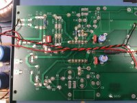 6 Photo of PA05 PCB.jpg493.3 KB · Views: 126
 -
 7 PA05 Grounding Topology Mod 1.jpg55.6 KB · Views: 127
 -
 8 REG-05 LM337 T Circuit Card.jpg44 KB · Views: 116
Thanks for the new info.
You make a good point about the amp package not having a ground pin. Most opamps don't have a ground pin and the PA05 is pretty much an opamp on steroids.
I don't see anything in the regulator board layout that is concerning. I recall one of your schematics implied relatively little regulator drop-out headroom (30V at reg input, 28V at reg output). Is there in fact generous dropout margin? Hum ingress remains a mystery. On the other hand, most power amps don't employ regulators anyway--- their power supply rejection is sufficient to yield good performance and PA05 specs suggest good hum rejection.
Later today, I'll try to sketch my thoughts re connection, for what they're worth.
It should. Even quite large (1.7MB). Report the refusal in the SITE section.the site would not accept a PDF
Attachments
Hi ceulrich,
I’m very sorry I’ve been so slow in responding.
I doubt safety ground is a culprit, but I suggest adopting the common technique of connecting AC safety ground through a pair of anti-parallel hefty power diodes so that a few tenths of a volt between the chassis and power ground won’t provoke hum currents. See for example https://www.diyaudio.com/community/threads/question-on-chassis-ground.385335/ post 7.
I ‘m still uncertain how 120Hz hum is finding its way into the amplifier and then, given hum is present, why does IM result rather than more benign linear superposition. Re IM, I’m still suspicious about the anti-parallel diodes between amp inputs, and I suggest disabling this path experimentally for possible reduced distortion. If you are uncomfortable abandoning the diode protection across the amp inputs, I’d recommend using 3 series diodes as the app note suggests, eg CR3,5,7 rather than only CR3. Diode conductance rises exponentially with applied voltage; consequently attenuating the applied voltage across each diode by a factor of 3 will reduce any non-linear currents far more than three-fold. Additionally, you’re also using R7 =10K. This increases distortion susceptibility compared to the 1K prescribed in an Apex note. I would suggest a post-jumper option to enable the shunting path—- makes experimenting less tedious.
Another IM mechanism might be the regulators. There doesn’t seem to be a lot of dropout margin and if these ICs switch out-of and into regulation dynamically in concert with the beat note between hum and the input, that’s IM.
Even if the regulators are an IM generator, it’s not clear how the IM would find its way into the amplifier. Further, in principle regulated supplies shouldn’t be needed to get good performance. You could experiment with bypassing the regulators by simply shorting together the IC’s three pins, leaving all other components in place.
Grounding techniques are a controversial topic, but my humble opinions follow (and I apologize in advance for my pitiful sketches and photography):
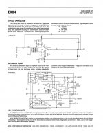
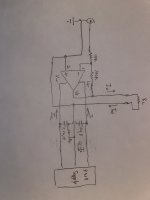
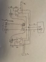
For a place to start discussion, let’s assume the amplifier shown in the first pic and stipulate that it does exactly what it should—-it somehow manages to deliver a distortion free sinusoidal voltage on its output pin, V0, with respect to the module +/- inputs. Assuming a linear load resistance tied between the module output and + input, I0 is therefore a distortionless current that must flow from the power supply common, since current drawn from the input should be negligible. The power supply is presumed to be “floating” so that only supply leakage currents flow to the ground connection at the input jack.
Dynamic supply currents are interesting. I1 is highly non-linear as it sources the positive half of the load current, I2 the negative. To a first order, dynamic I1 and I0 currents are near equal during the positive half-cycle, and similarly I2 and I0 are near equal on the negative half-cycle. Departures from match may be distortion currents and are absorbed by the power supply and by C4, C16. As you noted earlier, the PA05 module has no ground terminal, so where to connect C4, C16? It’s important that the opamp + input be tapped as shown, away from the C4, C16 junction, to avoid sensing distortion perturbations; on further refection, I believe they should simply float, unconnected, to avoid any distortion currents. I suggest Rx be 100K to simply avoid an indeterminant voltage at the C4, C16 junction and to ease probing the C4, C16 junction—- might be interesting. For discussion of opamp bypassing, see https://www.analog.com/media/en/technical-documentation/application-notes/AN-202.pdf
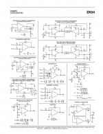
For a mono power amp, the first sketch depicts my connection instincts/recommendations. The connection of the amplifier board to the power supply is via twisted triple; note that net currents sum to near 0 so that there should be near 0 radiated magnetic fields. Same applies to currents to the speaker load. Lastly, twisted pair or shielded cable connects module to input jack and defines signal ground. Low radiated fields should also mean low susceptibility to hum fields, but I still suggest routing cabling away from the transformer and power supply to the extent possible.
The situation is more complex for a dual channel amplifier with because of its shared power supply, but I’d try to apply the same principles, namely keeping current flows balanced to minimizes radiated fields. The second sketch depicts my thoughts and I've not shown the C4, C16 caps for clarity. I’d distribute power along twisted runs, keeping the runs between the two boards as short and direct as practical. Tap at mid point between amp boards for the run to the shared power supply, again using twisted cabling.
I suggest using coax for the input wiring and connecting both shields at the junction of both speaker “ground” returns where they join for return to power supply common. The outer shield provides the connection for amp modules + input pin, and the shared “star” connection implies a single qui-potential “ground” at both module inputs, input jacks, and the chassis, and minimal currents flow from the star joint to the chassis ground connection.
Though the coax ostensibly shields the input, I still advocate dressing the coax alongside the power cabling (net 0 fields) and and around the perimeter of the chassis to the volume control and input jacks—- i.e. away from the power transformer. I hope all this is decipherable.
Please keep us posted. Good luck!
Steve
I’m very sorry I’ve been so slow in responding.
I doubt safety ground is a culprit, but I suggest adopting the common technique of connecting AC safety ground through a pair of anti-parallel hefty power diodes so that a few tenths of a volt between the chassis and power ground won’t provoke hum currents. See for example https://www.diyaudio.com/community/threads/question-on-chassis-ground.385335/ post 7.
I ‘m still uncertain how 120Hz hum is finding its way into the amplifier and then, given hum is present, why does IM result rather than more benign linear superposition. Re IM, I’m still suspicious about the anti-parallel diodes between amp inputs, and I suggest disabling this path experimentally for possible reduced distortion. If you are uncomfortable abandoning the diode protection across the amp inputs, I’d recommend using 3 series diodes as the app note suggests, eg CR3,5,7 rather than only CR3. Diode conductance rises exponentially with applied voltage; consequently attenuating the applied voltage across each diode by a factor of 3 will reduce any non-linear currents far more than three-fold. Additionally, you’re also using R7 =10K. This increases distortion susceptibility compared to the 1K prescribed in an Apex note. I would suggest a post-jumper option to enable the shunting path—- makes experimenting less tedious.
Another IM mechanism might be the regulators. There doesn’t seem to be a lot of dropout margin and if these ICs switch out-of and into regulation dynamically in concert with the beat note between hum and the input, that’s IM.
Even if the regulators are an IM generator, it’s not clear how the IM would find its way into the amplifier. Further, in principle regulated supplies shouldn’t be needed to get good performance. You could experiment with bypassing the regulators by simply shorting together the IC’s three pins, leaving all other components in place.
Grounding techniques are a controversial topic, but my humble opinions follow (and I apologize in advance for my pitiful sketches and photography):
For a place to start discussion, let’s assume the amplifier shown in the first pic and stipulate that it does exactly what it should—-it somehow manages to deliver a distortion free sinusoidal voltage on its output pin, V0, with respect to the module +/- inputs. Assuming a linear load resistance tied between the module output and + input, I0 is therefore a distortionless current that must flow from the power supply common, since current drawn from the input should be negligible. The power supply is presumed to be “floating” so that only supply leakage currents flow to the ground connection at the input jack.
Dynamic supply currents are interesting. I1 is highly non-linear as it sources the positive half of the load current, I2 the negative. To a first order, dynamic I1 and I0 currents are near equal during the positive half-cycle, and similarly I2 and I0 are near equal on the negative half-cycle. Departures from match may be distortion currents and are absorbed by the power supply and by C4, C16. As you noted earlier, the PA05 module has no ground terminal, so where to connect C4, C16? It’s important that the opamp + input be tapped as shown, away from the C4, C16 junction, to avoid sensing distortion perturbations; on further refection, I believe they should simply float, unconnected, to avoid any distortion currents. I suggest Rx be 100K to simply avoid an indeterminant voltage at the C4, C16 junction and to ease probing the C4, C16 junction—- might be interesting. For discussion of opamp bypassing, see https://www.analog.com/media/en/technical-documentation/application-notes/AN-202.pdf
For a mono power amp, the first sketch depicts my connection instincts/recommendations. The connection of the amplifier board to the power supply is via twisted triple; note that net currents sum to near 0 so that there should be near 0 radiated magnetic fields. Same applies to currents to the speaker load. Lastly, twisted pair or shielded cable connects module to input jack and defines signal ground. Low radiated fields should also mean low susceptibility to hum fields, but I still suggest routing cabling away from the transformer and power supply to the extent possible.
The situation is more complex for a dual channel amplifier with because of its shared power supply, but I’d try to apply the same principles, namely keeping current flows balanced to minimizes radiated fields. The second sketch depicts my thoughts and I've not shown the C4, C16 caps for clarity. I’d distribute power along twisted runs, keeping the runs between the two boards as short and direct as practical. Tap at mid point between amp boards for the run to the shared power supply, again using twisted cabling.
I suggest using coax for the input wiring and connecting both shields at the junction of both speaker “ground” returns where they join for return to power supply common. The outer shield provides the connection for amp modules + input pin, and the shared “star” connection implies a single qui-potential “ground” at both module inputs, input jacks, and the chassis, and minimal currents flow from the star joint to the chassis ground connection.
Though the coax ostensibly shields the input, I still advocate dressing the coax alongside the power cabling (net 0 fields) and and around the perimeter of the chassis to the volume control and input jacks—- i.e. away from the power transformer. I hope all this is decipherable.
Please keep us posted. Good luck!
Steve
Attachments
Hello Steve,
Thanks for all the effort you have put into this analysis, an explanation of the theory is very helpful.
I have been making various modifications over the past few days, and with some success. A lot of dumb luck and not much analysis, I am afraid. I will post my results shortly. I want to study your comments, but after a quick read, and considering some of the results I have obtained, the connection point for the star ground to the PCB ground plane seems critical.
In your 7th paragraph you mention Rx, what is Rx?
Cheers,
ceulrich
Hi ceulrich,
Rx conveys uncertainty. Initial inclination was Rx=0, as bypassing of +/- opamp rails to "ground"is so commonplace. But Bob Cordell's book advises making sure that attachment of amp bypassing doesn't corrupt sensing of signal ground, and I recalled that old note re bypass. So that led to the notion that Rx should be open, i.e. bypass is series connection of C4 and C16, to avoid any contamination with distortion currents through C4+C16. Final nuance was to set Rx=100K, negligible for distortion contribution, but sets junction to ~0V for easy probing with a scope probe. I thought probing that point might be insightful, but scope sensitivity may be too low.
I'm going to be away on vacation so won't be able to checkin consistently. Good luck!
I'm interested in this as well. I'm building an amp based on the PA85 (200 ma/450V) for some test applications.
The symptoms could be an indication of oscillation in either the amp or the power supplies. The Apex amps are all pretty wideband which can get you into trouble. Apex has spice models that seem pretty good. It would not take long to recreate the circuit in LTspice to see what is happening.
With a blocking cap you can use the QA401 to look at the power supplies to see if they are dropping out of regulation or ? However you need a wide band (50 MHz+) scope to look for oscillations. When looking at the amp output its important to use the QA401's differential input and you can then see what is happening in the grounds. You can even see ground currents (voltage drop) across the various ground returns which may help localize the source of the distortion/noise.
- Home
- Amplifiers
- Chip Amps
- Apex PA05 Power Op Amp as an audio amp