Hello All,
Like most DIYers I have chased ground loops down various rabbit holes more than once. I have concluded that finding the correct grounding topology is similar to setting up a cartridge, all settings (or ground connections) are interrelated.
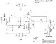
Before I proceed, let me make a clarification. Let’s go back to post #29 for a moment. The grounding topology shown was as the amp was originally built and how this recent saga started. What was implied but not specifically illustrated, is that the star ground point is also the chassis safety ground point. I am not sure how important that specific point is, but I wanted to make the clarification. Note that the input phono connectors and the speaker connectors are isolated from the chassis. The PCB and the PA05 are isolated from the chassis. I have checked, and they are indeed all isolated.
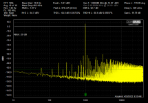
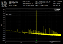
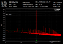
Over the past week or two I have tried many grounding modifications, some suggested by your comments. I will just mention a few: 1 - Running a 3-twist power wiring to the circuit card, made no difference. 2 - Breaking the connection between the star ground and the 115V third wire ground, made no difference. 3 - Placing a 10 ohm resistor between the 115V third wire ground and the star ground made no difference. 4 - Added more power supply bypassing close to the chip pins, at C9 and C11, this did not seem to have much effect. 5 – Tying the star ground to the amps positive input made no improvement (see attachment 1). 6 – Moving that star ground wire to the ground plane of the PCB at R12 made an incremental improvement (see attachment 2)
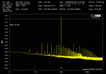
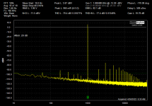
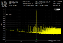
Note from Post #1 the photo with the amp opened up. All the testing so far has been accomplished with that geometry . Occasionally I have noted strange differences in readings from day to day. This prompted me look into the isolation or not of the chassis top. Attachment 3 shows the distortion spectrum with the chassis top floating. Attachment 4 shows the spectrum when the chassis top is firmly connected to the rest of the chassis, as would occur once it is put back together again. Some incremental improvement is noted.
The 120Hz IM is still a problem.
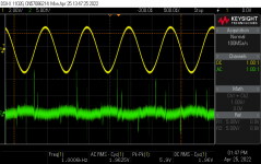
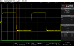
1audio, thanks for the comments. The oscillograph in Attachment 5 shows the amp output on channel one and the output through a 1KHz notch filter on channel 2 (1KHz at 1W / 4 Ohm). I see some crossover distortion, maybe someone else will see a lot more🙂.
Cheers,
ceulrich
Like most DIYers I have chased ground loops down various rabbit holes more than once. I have concluded that finding the correct grounding topology is similar to setting up a cartridge, all settings (or ground connections) are interrelated.
Before I proceed, let me make a clarification. Let’s go back to post #29 for a moment. The grounding topology shown was as the amp was originally built and how this recent saga started. What was implied but not specifically illustrated, is that the star ground point is also the chassis safety ground point. I am not sure how important that specific point is, but I wanted to make the clarification. Note that the input phono connectors and the speaker connectors are isolated from the chassis. The PCB and the PA05 are isolated from the chassis. I have checked, and they are indeed all isolated.
Over the past week or two I have tried many grounding modifications, some suggested by your comments. I will just mention a few: 1 - Running a 3-twist power wiring to the circuit card, made no difference. 2 - Breaking the connection between the star ground and the 115V third wire ground, made no difference. 3 - Placing a 10 ohm resistor between the 115V third wire ground and the star ground made no difference. 4 - Added more power supply bypassing close to the chip pins, at C9 and C11, this did not seem to have much effect. 5 – Tying the star ground to the amps positive input made no improvement (see attachment 1). 6 – Moving that star ground wire to the ground plane of the PCB at R12 made an incremental improvement (see attachment 2)
Note from Post #1 the photo with the amp opened up. All the testing so far has been accomplished with that geometry . Occasionally I have noted strange differences in readings from day to day. This prompted me look into the isolation or not of the chassis top. Attachment 3 shows the distortion spectrum with the chassis top floating. Attachment 4 shows the spectrum when the chassis top is firmly connected to the rest of the chassis, as would occur once it is put back together again. Some incremental improvement is noted.
The 120Hz IM is still a problem.
1audio, thanks for the comments. The oscillograph in Attachment 5 shows the amp output on channel one and the output through a 1KHz notch filter on channel 2 (1KHz at 1W / 4 Ohm). I see some crossover distortion, maybe someone else will see a lot more🙂.
Cheers,
ceulrich
Attachments


I would first separate the safety ground from the signal ground. A 50 Ohm resistor between them is enough isolation usually but disconnect for testing to make sure you do not have a ground loop. The QA USB interface is isolated but you can still get noise coupling through it.
The HF spikes in sync with the signal are a little distressing as well. Are they modulating with the power line?
The HF spikes in sync with the signal are a little distressing as well. Are they modulating with the power line?
Hello All,
Making some real progress now!
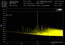
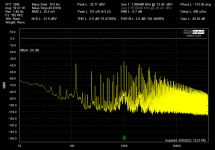
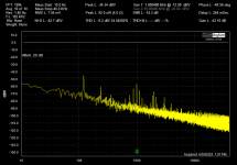
Steve’s idea of shorting out the regulators was attractive due to its simplicity. Attachment 1 shows the distortion spectrum with the regulators operating normally. Attachment 2 shows the spectrum with the regulators shorted. Attachment 3 shows the spectrum using an unregulated external power supply. It looks like the problem is with the regulators.
I think my options now are to troubleshoot the regulators and see if they are fixable, or to scrap the regulators and run with an unregulated supply.
Suggestions welcome.
Cheers,
ceulrich
Making some real progress now!
Steve’s idea of shorting out the regulators was attractive due to its simplicity. Attachment 1 shows the distortion spectrum with the regulators operating normally. Attachment 2 shows the spectrum with the regulators shorted. Attachment 3 shows the spectrum using an unregulated external power supply. It looks like the problem is with the regulators.
I think my options now are to troubleshoot the regulators and see if they are fixable, or to scrap the regulators and run with an unregulated supply.
Suggestions welcome.
Cheers,
ceulrich
Attachments

Looking more carefully at your supply. First do you need a regulated supply? A regulator has to maintain voltage at peak current. For a power amp that's a lot of current. For that chip into 4 Ohms that's 10A. at 30V or 300W + and 300W -. That is why regulated supplies are rare in power amps.
However you may get the benefits of regulation from the +/- boost supplies which do not need much power looking at the small switchers they use.
Second the shared ground on the supply board is not helping. And the ground return from the amp board to the power supplies (cut them apart +/- and use separate wires) should connect to the common point of the on board bypass caps. The ground should all go to that common point. I can't see in the pictures or the documents where the intended connection for ground is on the board or how it connects between the ground wire from the input to the common of the caps. A quick test would be to tie a wire from the common between C5 and C11 and the power ground. Then from that connection to the return connection from the output.
You can use the QA401 to look at the supplies. You will need a DC block. If the regulators are misbehaving you should see the grunge in the output change as you drive the amp in level. it should also be visible on a scope. Its possible there is a loop causing instability. You may need to decouple the regulators outputs with some small inductance. When you connected the external supply where did you connect it?
Useful insights, ceulrich!
I suspect the dramatic difference in the third picture might be an issue of shielding. The external unregulated supply would have the advantage of distance and some intervening enclosure shielding.
You might try using your audio analyzer to compare IM distortion products at the power supply terminals, but I would be surprised if the IM voltages seen on the external supply terminals were vastly different from the internal power supply; rather with the external PS, I suspect the amp just enjoyed better isolation from all the IM crud generated within the PS.
Try separating the amp heatsink "lid" from the power supply as much as wiring slack allows, but be sure to bond the lid to PS chassis. Does increasing distance between amps and power supply help the issue?
If so, try adding some shielding between amps and power supply to try for compatibility of amps and PS within the shared enclosure. In challenges akin to this, I’ll sometime enclose some aluminum foil inside a zip-lock bag for insulation, with a short ground wire brought out from the foil to connect to chassis ground. Sometimes experiments like this are sufficient to prove a shielding concept for subsequent fabrication. Often the interference is magnetic rather than mere voltage fields. Then sometimes galvanized steel rather than foil (eg. furnace duct from Home Depot) suffices, but magnetic shielding is often a lot tougher to cure. Experimentation is the order of the day.
Tonight is probably my last post for a couple of weeks. Seems like you’ve already got a lead on the problem. Good luck!
Steve
Hello All,
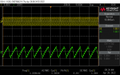
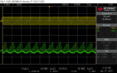
I took 1audio’s suggestion of looking at the power supply output with the scope. The results are not encouraging. The attached oscillographs show the amplifier output (1KHz signal at 1 watt into a 4 ohm load) on channel 1 and either the unregulated or regulated power supply output on channel 2. Attachment 1 is the unregulated supply and Attachment 2 is the regulated supply. The unregulated supply has about 300mVpp of 120Hz ripple while the regulated has about 90mVpp.
It is not clear to me that if I just eliminate the regulators and use the unregulated supply I will be any better off. The unregulated PS cards are not positioned well for that use, so I will probably have to rearrange the components within the chassis. Then the question is, why not just replace them with a properly designed PS.
I will think on this for a bit before I make a decision.
Cheers,
ceulrich
Attachments
I think there is something not right in ground references here. The regulators seem to be falling out of regulation on the peaks. My next step would be to look at the chip itself differentially, between the ref pin and the output pin. I would also look between the ref pin and the negative speaker connector. There should be millivolts of ripple in both cases. 1.4V across 4 Ohms load is a peak current 350 mA. That should be well within the range of a LM337. It looks like the regulator may be referencing something that is not at the star ground level. The high level of 1 KHz ripple on the supply ripple suggests that the bypass caps at the amp are not working right.
Seperate question- will the LM337 handle the peak current in your application?
Have you confirmed your 4 Ohm load is 4 Ohms? Sometimes you need to check everything.
Seperate question- will the LM337 handle the peak current in your application?
Have you confirmed your 4 Ohm load is 4 Ohms? Sometimes you need to check everything.
Hello All,
Before moving on to dealing with the regulators, I thought I would clean up some loose ends.
1audio brought up the issue of amplifier oscillation a few days ago, and at the time the amp was not oscillating.
More than one contributor has suggested separating the star ground from the safety ground, and I thought that was well worth trying. However, while trying that, I discovered that if the star ground is floated, the amplifier goes into oscillation at 1.78MHz. I do not understand the mechanism. I added a Zobel network (10 ohms – 0.1MFD) on the output to control this oscillation. So, I can now make that comparison. Attachment 1 shows the distortion spectrum with the star ground and the safety ground connected, while Attachment 2 shows the spectrum with a floating star ground. There is essentially no difference. I repeated the experiment of placing a 10-ohm resistor between the safety ground and the floating star ground (simulating the bridge rectifier type ground lift circuit), again no difference.
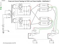
It has also been suggested that separating the grounds between the two amplifiers might help. So, I scrapped the single point star ground concept, and rewired the power as shown in Attachment 3. I had high hopes for this, I liked the idea a lot, but as shown in Attachment 4, that made things a bit worse. Note, these new connections are a bit sloppy, the amplifier looks more like a breadboard affair than a finished product, but I do not think “dressing” all the wiring properly will be the magic bullet.
Cheers,
ceulrich
Before moving on to dealing with the regulators, I thought I would clean up some loose ends.
1audio brought up the issue of amplifier oscillation a few days ago, and at the time the amp was not oscillating.
More than one contributor has suggested separating the star ground from the safety ground, and I thought that was well worth trying. However, while trying that, I discovered that if the star ground is floated, the amplifier goes into oscillation at 1.78MHz. I do not understand the mechanism. I added a Zobel network (10 ohms – 0.1MFD) on the output to control this oscillation. So, I can now make that comparison. Attachment 1 shows the distortion spectrum with the star ground and the safety ground connected, while Attachment 2 shows the spectrum with a floating star ground. There is essentially no difference. I repeated the experiment of placing a 10-ohm resistor between the safety ground and the floating star ground (simulating the bridge rectifier type ground lift circuit), again no difference.
It has also been suggested that separating the grounds between the two amplifiers might help. So, I scrapped the single point star ground concept, and rewired the power as shown in Attachment 3. I had high hopes for this, I liked the idea a lot, but as shown in Attachment 4, that made things a bit worse. Note, these new connections are a bit sloppy, the amplifier looks more like a breadboard affair than a finished product, but I do not think “dressing” all the wiring properly will be the magic bullet.
Cheers,
ceulrich
Attachments

There should not be that interaction with the "safety" ground. It suggests some not obvious connection somewhere. Can you measure the DCR between the power supply ground, the signal ground connection, the low side of the input connectors and then the common on the output bypass caps? The data from Apex is not clear about that ground connection on the PCB and verifying that all the ground are connected is important.
When you had it connected to the external supply was the safety ground open? it seemed to be clean then.
When you had it connected to the external supply was the safety ground open? it seemed to be clean then.
1audio, thanks for your continued interest and suggestions.
Cleaning up more loose ends:
My dummy load measures 4.11 ohms using a DMM, and not correcting for any test lead resistance.
Regarding the question – will the LM337 handle the peak current? That is a good point to make. As I noted, I originally selected the regulators because I had them available, and I knew I was operating the PA05s with little or no heatsinking, so I would not be able to draw a lot of current. The original Linear Technology data sheet specs a current limit of 2.2A. That would give me somewhere around 4A or about 25 watts. I recently measured the clipping level with a 7.5 ohm load, it was 14.4Vrms, for 27.6W and 1.92A, which is in line with my original assumptions. Assuming I did the math right. Of course, as you noted, the 1W load should not stress the LM337 at all.
I set up the QA401 for differential measurement with a 1MFD capacitor in each leg. With the amplifier operating with a 1KHz signal at 1W into 4 Ohms, I made measurements on the negative leg of the negative regulator (I am assuming the term reference pin is the same as the datasheet’s adjustment pin): Attachment 1, shows the distortion spectrum between output and ground of that regulator. Attachment 2, spectrum between the reference pin and the output pin. Attachment 3, spectrum between the reference pin and the negative speaker terminal. My reading of this data is that the 120Hz noise is at about 13mV or less, which would probably be considered low, do you agree?
I agree that some stray ground connection could be in play, but I have spent a lot of time looking for it, and have not found it. The resistance between the PS ground and the low side of the input connector is 0.087 ohms. I am not sure what the “common on the output bypass caps” is.
At this point I am giving serious consideration to scrapping the regulators.
Cheers,
ceulrich
Attachments

Yes, I would remove the regulators because, for your positive regulator, you are using a negative regulator wired in reverse. In this case the reference for 377 chip is the fluctuating positive rail and the chip is trying to regulate the ground in response. If you really want a regulated power supply, you may want to try a true complimentary positive/negative regulator instead. This may not be 100% of the problem but it looks very suspicious to me.
Attachments
I looked at the PA-05 spec - did you realize the chip has separate power supply inputs for the output stage and driver stage? Apparently the power supply value can be greater for the output stage as well. I would think putting the regulated voltage to the driver power supply inputs and the unregulated to the output stage may be of benefit.

“common on the output bypass caps” : C5 and C16 should have a common connection that would return to the power supply ground.
The regulators could be oscillating. You should be able to see that on the scope. Its a little odd seeming to use two negative regulators, however there may be some reason, like lower noise?? They are two isolated floating supplies so its not that critical.
The amp module has a Vboost circuit. The amp is built from power MOSfets. They typically have a 3V threshold so you need to drive the gates 3V higher than the drain to max output. I would use a regulated supply for the Vboost connections but follow the datasheet numbers for the voltages. The regulated supply will need to be higher than the power rails which would mean a separate DC supply. I have done that and it worked extremely well.
General observations:
diode rectifiers will be an unavoidable generator of IM products but they should be suppressed by a property working amplifier. A properly working regulator should should also suppress IM present at its input, but nonetheless not be necessary in the amplifier system. My own prejudice would be to dispense with the regulators.
I suggest returning to your experiment with the external unregulated PS. It suggested promising performance if I’m not mistaken? Use that configuration to test the desirability of joining the C4/C16 bypass into the PS common and ground system, ie stability and distortion. If you’re lucky, this may be a convenient platform to explore other grounding conundrums.
Admittedly I’m talking big leaps here, but try to pursue the amp system as far as you can toward a complete system, albeit with external PS. Then try applying power to the unconnected internal PS. Anything misbehaving? Add internal PS common only; misbehaving? If appropriate, try adding DC loads to internal PS so that they have to deliver power but are otherwise unconnected. You’re looking for intrusion of hum into amplifier output Proximity/lack of adequate shielding between amps and PS may come into play. Try to find the boundary between working/not working to zero toward issues.
Always, good luck!
Hello All,
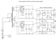
Things are really looking up. I removed the regulators and rewired the existing unregulated supply. Attachments 1 and 2 show the distortion spectrums for the left and right channels, respectively. The current schematic is shown in Attachment 3. The Zobel network is only needed on the left channel. I took a quick look at the 10KHz square waves, and there is a bit more ringing on the left channel. I have spent the past few months working almost exclusively on the left channel, so I probably have a bad joint somewhere that I need to find. The current power and grounding topology is shown in Attachment 4.
Cheers,
ceulrich
Attachments

That looks much better. RE headphone- I think you need more attenuation. A 100 Ohm series resistor really is not enough to prevent unpleasant, and possibly damaging surprises. Maybe a parallel 10 Ohm resistor with the headphone?
Hello All,
I thought I would post some measurement data on the modified amplifier. First, a change to the schematic in Post # 55. I found that removing the Zobel network and adding a 5pF compensation capacitor across the R1 the feedback resistor, eliminated the tendency to oscillate and it cleaned up the ringing on 10KHz square waves. I will be implementing 1audio’s suggestions on the headphone output.
With the revised power supply, the clipping level is 13.8Vrms across 4 ohms for about 47W. That is high enough that I will probably have to worry about adequate heatsinking.
Attachment 1 shows the 10KHz square wave. Attachments 2, 3 and 4 shows frequency response, and THD+N vs frequency and output power, respectively.
All told, I think I have a nice little amp now. I am looking forward to hear how it sounds.
Cheers,
ceulrich
Attachments
Nice to see your progress and success.
In case you're wondering about the use of a regulated power supply, here's how Douglas Self summarizes the subject in his book - Audio Power Amplifier Design Handbook, 5th Ed,. page 269
"The generic amplifier designs examined in this book have excellent supply-rail rejection, and
so a simple unregulated supply is perfectly adequate. The use of regulated supplies is definitely
unnecessary, and I would recommend strongly against their use. At best, you have doubled the
amount of high-power circuitry to be bought, built, and tested. At worst, you could have intractable
HF stability problems, peculiar slew-limiting, and some expensive device failures."
Hello All,
Sorry to take so long to respond, but spring finally arrived here in mid-Ohio, so I had to abandon the test bench for outdoor work.
techtool, thanks for the encouragement. The quote from Self does seem to predict the type of problem I encountered.
After all these years, I am now convinced that the PA05 does make a very fine audio amplifier. Over the last few days, I have had a chance to do some serious listening. I compared it to the system in my family room, consisting of an Oppo UDP-203 disc player, Cambridge AXR 100 receiver and a pair of Phase Technology PC80 mini-monitors. I did level matching using pink noise at about 0.55VAC at the speaker terminals. I made this measurement with an old Extec handheld DMM, so I suspect it is more like an average rather than RMS measurement. This resulted in an SPL of about 78dBA in the room. Which is a little bit less than my normal listening level. This put the volume control at about the ¾ point. My main system uses Magnepan speakers which need way more power than this little amp could provide.
I listened to some tracks from Stereophile’s Editor’s Choice CD. The main difference I heard was a little bit brighter high end for the PA05 amp. The solo violin from track 7 sounded brighter or more crystal clear, exemplified by the plucked note at the very end, which just popped a lot more than with the Cambridge amp. I think this is going to make a mighty fine little amp for the office.
Once again, thanks to everyone that offered advice and suggestions they were very helpful. This has turned out to be an enjoyable learning experience, and I got a new amp in the process.
Cheers,
ceulrich
- Home
- Amplifiers
- Chip Amps
- Apex PA05 Power Op Amp as an audio amp