Hi everyone.. I really appreciate that apex power amps are so famous in my country. Expecially B500 type.
I have a question of this A40. Can I add some more final power transistors to make it more powerful? If yes, will it affect the fidellity?
I have a question of this A40. Can I add some more final power transistors to make it more powerful? If yes, will it affect the fidellity?
Acording to onsemiconductor website bc560c is obsolete ...
https://www.onsemi.com/products/discretes-drivers/general-purpose-and-low-vcesat-transistors/bc560c
Can i use bc556/bc546 instead of bc550/bc560 in a40 amplifier?
Thanks.
https://www.onsemi.com/products/discretes-drivers/general-purpose-and-low-vcesat-transistors/bc560c
Can i use bc556/bc546 instead of bc550/bc560 in a40 amplifier?
Thanks.


2.1channel system
2 channel bridges for subwoofer
Nice work, can you share your regulated PSU?
Regards
hi all i have a problem in a 40. by turning ofset pot, ofset voltage drops but becomes constant at 2.5v dc even when pot is fully turned. i tried to figure it out but could not find any thing. other channel is working without any issue.. can any one help me?
Visaton speakers?
Exactly.
Visaton Concorde.
Visaton Concorde Mk III - Speaker KIT without Cabinet buy at hifisound.de
Visaton Concorde.
Visaton Concorde Mk III - Speaker KIT without Cabinet buy at hifisound.de
Hi, I hope you are doing great, do you have the layout of this regulated power supply? or the Gerber files
Hi all,
The latest revision of PCB 😀 Will be ready this summer . 😀
BR Alex
Hey Alex mm - any chance you would post gerbers of this new version? By the way thanks for the previous version, which I will use if the new version is not available.
Trying to find a <200mmx100mm board to replace 2 blown channels in a NAD 5-channel amp and this looks to be the most highly recommended I can find.
Thanks,
Paul
estou com problema de captação de ruído no a40,ja retirei o transformador e a fonte estabilizada do gabinete e nada do ruido acabar,acho que o ruido esta no pcb,o terra está cobrindo os espaços vazios,alguem teve esse problema?
 Por favor, poste uma tradução. se não estiver postando em inglês. O Google Translate está bom.
I have a problem with noise capture on the a40, I already removed the transformer and the stabilized source from the cabinet and nothing stopped, I think the noise is on the PCB, the ground is covering the empty spaces, did anyone have this problem?
Por favor, poste uma tradução. se não estiver postando em inglês. O Google Translate está bom.
Last edited by a moderator:
Please,
Contact me by PM. I faced lots of this kind of problem in Telecom area where the telephone got local radio and PX.
It support will cost you a pair of bare boards for layout evaluation and possible solution related to the board.
Ronaldo
Contact me by PM. I faced lots of this kind of problem in Telecom area where the telephone got local radio and PX.
It support will cost you a pair of bare boards for layout evaluation and possible solution related to the board.
Ronaldo
Last edited:
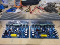
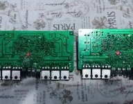
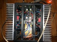
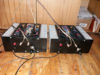
Hello all Apex fans.
I can't wait to show you how we turned the A40 into a real monster.
There is more work to do, but I will show what we have been through so far.
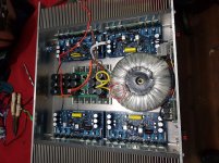
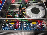
Of course, the concept consists of 2 monoblocks.
We removed the 52 volt power supply.
We replaced many of the circuit board elements ..... terminal transistors, capacitors, resistors .....
We added a 100 pico capacitor to the servo to improve the frequency response of both electrolytes.
We set the rest current to 600mA by putting the circuit boards in 39 watts pure Class A.
2 boards work in bridge mode up to 300 watts.
Sound cannot be described in words.
Control of the speakers is palpable.
When I'm done with the exterior design, I'll show it to you and let you hear it.😀
Greetings to everyone, and I was super excited about building this excellent amplifier.
I can't wait to show you how we turned the A40 into a real monster.
There is more work to do, but I will show what we have been through so far.
Of course, the concept consists of 2 monoblocks.
We removed the 52 volt power supply.
We replaced many of the circuit board elements ..... terminal transistors, capacitors, resistors .....
We added a 100 pico capacitor to the servo to improve the frequency response of both electrolytes.
We set the rest current to 600mA by putting the circuit boards in 39 watts pure Class A.
2 boards work in bridge mode up to 300 watts.
Sound cannot be described in words.
Control of the speakers is palpable.
When I'm done with the exterior design, I'll show it to you and let you hear it.😀
Greetings to everyone, and I was super excited about building this excellent amplifier.
Attachments

Last edited:
Hello all Apex fans.
I can't wait to show you how we turned the A40 into a real monster.
There is more work to do, but I will show what we have been through so far.
Of course, the concept consists of 2 monoblocks.
We removed the 52 volt power supply.
We replaced many of the circuit board elements ..... terminal transistors, capacitors, resistors .....
We added a 100 pico capacitor to the servo to improve the frequency response of both electrolytes.
We set the rest current to 600mA by putting the circuit boards in 39 watts pure Class A.
2 boards work in bridge mode up to 300 watts.
Sound cannot be described in words.
Control of the speakers is palpable.
When I'm done with the exterior design, I'll show it to you and let you hear it.😀
Greetings to everyone, and I was super excited about building this excellent amplifier.
Nice work,
Regards
Hi all, what is the minimum voltage for the A40 using two 2Sc5200 and two 2SA1943? I have about a 43-0-43 which is about 60-0-60vdc
it looks excellent,but it is not 39W A-class amplifier with 600mA bias. with 8r loudspeaker it is 2,88W A-class amplifier,and with 4r it is 1,44W A-class amplifier. anyway,I have no doubt that it sounds great!Hello all Apex fans.
I can't wait to show you how we turned the A40 into a real monster.
There is more work to do, but I will show what we have been through so far.
Of course, the concept consists of 2 monoblocks.
We removed the 52 volt power supply.
We replaced many of the circuit board elements ..... terminal transistors, capacitors, resistors .....
We added a 100 pico capacitor to the servo to improve the frequency response of both electrolytes.
We set the rest current to 600mA by putting the circuit boards in 39 watts pure Class A.
2 boards work in bridge mode up to 300 watts.
Sound cannot be described in words.
Control of the speakers is palpable.
When I'm done with the exterior design, I'll show it to you and let you hear it.😀
Greetings to everyone, and I was super excited about building this excellent amplifier.
Hi all, what is the minimum voltage for the A40 using two 2Sc5200 and two 2SA1943? I have about a 43-0-43 which is about 60-0-60vdc
Minimum would be ~30V +/-, however 60V is right at, probably past the 55V max for 2 pair outputs unless you have big heatsinks, running 8-ohm or higher loads only or use mjl/w3281 or 4281 big brother transistors.
- Home
- Amplifiers
- Solid State
- Apex A40 Amplifier Build Thread