
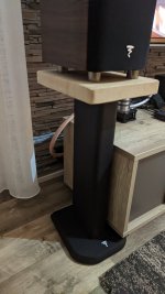
There is sandstone on the Focal stand. Due to its own weight, it is not attached to it.Nice. Carpet or hardwood floors?
Attachments
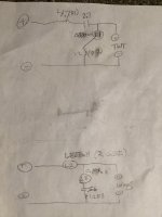
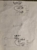
Ohhh..thank you..Is this a good schematic? I just wanted to write to focal support because of the circuit diagram and coil values.😉🥳Hey Balu80, what is your crossover challenge? Does this diagram help?
ohh...my litze coil has already arrived..had to wait 1 month for it...but not 1.227mh but only 1.2😳.Is L3 0.194mh?Hey Balu80, what is your crossover challenge? Does this diagram help?
1.2mh vs 1.227mh is only a 2% variance. It’s an acceptable variance for audio. In addition, I don’t have a professional meter so my readings may be off by more than 2%.
For comparison, one of the focal capacitors labelled 5.6uf measured 5.86uf.
For comparison, one of the focal capacitors labelled 5.6uf measured 5.86uf.
I understand. According to these, the values of the small coils can also differ somewhat? L1 / L31.2mh vs 1.227mh is only a 2% variance. It’s an acceptable variance for audio. In addition, I don’t have a professional meter so my readings may be off by more than 2%.
For comparison, one of the focal capacitors labelled 5.6uf measured 5.86uf.
Yes there will be a variance. Also it‘s unlikely your new parts will measure exactly as stated.
Thanks.you can go for jentzen superior, silver-z or mundorf supreme, these should be the easiest or say safest. going higher Alumen z-cap can be better than the last two, owing to low uf value it is also doable, also in the range would be supreme evo oil. this is great resource for capacitors https://www.humblehomemadehifi.com/Cap.html . Personally i would select any of these based on the what budget allows.
I could not understand why you chose to use expensive bypass capacitor and cheaper series capacitor, you should have used alumen z-cap or supreme evo oil and miflex bypass capacitor for tweeter circuit.
Hi all...A big Coil not 1,2 mH...
1,4 mH😡
If you remove the roll from the sticker, it is written there. With us, you have to wait more than 1 month for the Litze coil. I can't exchange it back because they don't have it in stock.
1,4 mH😡
If you remove the roll from the sticker, it is written there. With us, you have to wait more than 1 month for the Litze coil. I can't exchange it back because they don't have it in stock.
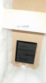
Interesting, when where your speakers manufactured? Mine have a QA stamp dated March 2015. Coils I removed didn’t have a sticker. See attached. Are you able to check the actual measurement? I replaced the stock coils with good quality 1.2mh coils. I have no desire to fall back to the original coils.
could you please share a pic?
could you please share a pic?
Attachments
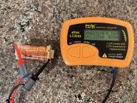
Thanks for the quick response. I can't take a picture of 1.4 with one hand, but this value is there. On the other hand, the small coil shows 0.2. I did not remove the third coil because you also measured the first one correctly.Interesting, when where your speakers manufactured? Mine have a QA stamp dated March 2015. Coils I removed didn’t have a sticker. See attached. Are you able to check the actual measurement? I replaced the stock coils with good quality 1.2mh coils. I have no desire to fall back to the original coils.
could you please share a pic?
Attachments
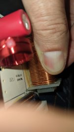

Is 1.4mh stamped on the circuit board? The coil in your pic looks exactly the same as I have.
your speaker is 2.5 years newer. Maybe the difference falls under the category specs are subject to change. Strange that the other components in your woofer circuit match specs I had previously shared. I suggest you try the 1.2mh coil.
your speaker is 2.5 years newer. Maybe the difference falls under the category specs are subject to change. Strange that the other components in your woofer circuit match specs I had previously shared. I suggest you try the 1.2mh coil.
Last edited:
yes, 1.4 is written on it. If you enlarge the picture, you can see the number 4.Is 1.4mh stamped on the circuit board? The coil in your pic looks exactly the same as I have.
your speaker is 2.5 years newer. Maybe the difference falls under the category specs are subject to change. Strange that the other components in your woofer circuit match specs I had previously shared with you. I suggest you try the 1.2mh coil.
I try 1.2 mh coil.
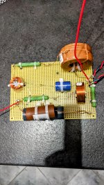
An experienced, good specialist changed the location of the resistors a little. He told me to do it as shown in the picture. I hope to post the pictures on Saturday. It will be a completely new crossover on a new board, soldered together at the legs. I'm so excited 🙂yes, 1.4 is written on it. If you enlarge the picture, you can see the number 4.
I try 1.2 mh coil.
Attachments
not yet. I will ask tomorrow because he is very busy.Cool. Did the specialist explain benefit of moving the resistors?
The answer came. I will try to translate the essence well because the answer was quite long. The sound wave travels in the direction. Based on such a consideration, it is somewhat reasonable to say that if there is resistance in front, then the sound signal passes through it first. Thus, the more delicate component behind it is exposed to somewhat less stress, it works less at its limits, which is generally good.Cool. Did the specialist explain benefit of moving the resistors?
In the series branch of the tweeter, i.e. on the positive wire, the resistor is first in line, and then the capacitor. Thus, the capacitor does not have to take up the entire load electronically. But it is also somewhat of a hifi design rule that the resistor should preferably be in front of the capacitor/coil. Sound quality experience too. Those two resistors next to each other are probably at the end of the line on the factory PCB table because it was easier to place them that way, and it was able to connect to the right places between the conductor tracks.
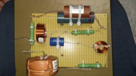
Hello! My friend and I did the crossover yesterday, but unfortunately for several reasons, the cable ran out. I have to go to Budapest on Monday because you can only get this variety there🤪.. It will be ready on Tuesday.Cool. Did the specialist explain benefit of moving the resistors?
Attachments
Your explanation makes sense. ThanksThe answer came. I will try to translate the essence well because the answer was quite long. The sound wave travels in the direction. Based on such a consideration, it is somewhat reasonable to say that if there is resistance in front, then the sound signal passes through it first. Thus, the more delicate component behind it is exposed to somewhat less stress, it works less at its limits, which is generally good.
In the series branch of the tweeter, i.e. on the positive wire, the resistor is first in line, and then the capacitor. Thus, the capacitor does not have to take up the entire load electronically. But it is also somewhat of a hifi design rule that the resistor should preferably be in front of the capacitor/coil. Sound quality experience too. Those two resistors next to each other are probably at the end of the line on the factory PCB table because it was easier to place them that way, and it was able to connect to the right places between the conductor tracks.
set it and let it play continuously for 3-4 days. then we are ready for your impressions.Hello! My friend and I did the crossover yesterday, but unfortunately for several reasons, the cable ran out. I have to go to Budapest on Monday because you can only get this variety there🤪.. It will be ready on Tuesday.
- Home
- Loudspeakers
- Multi-Way
- Anyone upgraded Focal Aria crossovers?