Hi,
First post so be gentle..
I've been meaning to join this forum for a while as I almost always end up coming across great information from here. I started my interest/vocation with electronics with audio and moved onto digital/power, well, its about time I got back into the swing of analogue audio design.
My first question is about repairing a Rel Storm III sub for a neighbour. It's an older 2002 model, and by the looks of things the bipolar driver transistors for the MOSFET have blown, taking a resistor with it. After contacting Sumiko about it, I managed to convince customer support to provide the value of he burnt resistor, and I have the datasheets for the driver transistors. (BFN16 NPN, and BFN19 for PNP). As these transistors are SMT SOT89 they can't dissipate much heat, which is probably why they have failed (even with a good copper heatsink on the PCB). They added through-hole footprints on the PCB in parallel, making it easier to use TO-220's (or TO-126) for replacements, so I was thinking, MJE340's and 350's?
I am not after 'improving' sound for my neighbour as he is happy with it, so the closer I get to BFN16/19 equivilents the better, and being a sub, high end frequency response is not an issue. I picked these transistors for availability, and their higher power dissipation, along with the possibilty of adding a heatsink.
There's also the MJE15034/35, which are most expensive, higher gain, greater power dissiaption, highg frequency response etc.. but I fear the high end won't be needed for a sub, plus, perhaps the higher gain would result in a change in sound, or require a change in the values of passives.
As cheeky as this is, if anyone owns a storm III, any cance you could post a pic of the power amp PCB? Specifically the driver transistors not the MOSFET's). I read that Rel upgraded the design in 2005 due to failures (most likely of this kind) so a picture of the later model would be ideal, as I could see any changes they made. As you can guess, Rel is understandably a bit hush hush on this, as they want money for repairs, plus, its a specialists field, for qualified 'rel engineers' only.
Ultimately, despite my (somewhat limited) understanding of audio electronics, I am not trying to reinvent the wheel. Purely to get the sub working again, as close to the original sound quality as posible, but improving reliability so parts don't overheat again. Hopefully he can enjoy another 10 years of it, without having to upgrade")
Cheers,
Buriedcode
First post so be gentle..
I've been meaning to join this forum for a while as I almost always end up coming across great information from here. I started my interest/vocation with electronics with audio and moved onto digital/power, well, its about time I got back into the swing of analogue audio design.
My first question is about repairing a Rel Storm III sub for a neighbour. It's an older 2002 model, and by the looks of things the bipolar driver transistors for the MOSFET have blown, taking a resistor with it. After contacting Sumiko about it, I managed to convince customer support to provide the value of he burnt resistor, and I have the datasheets for the driver transistors. (BFN16 NPN, and BFN19 for PNP). As these transistors are SMT SOT89 they can't dissipate much heat, which is probably why they have failed (even with a good copper heatsink on the PCB). They added through-hole footprints on the PCB in parallel, making it easier to use TO-220's (or TO-126) for replacements, so I was thinking, MJE340's and 350's?
I am not after 'improving' sound for my neighbour as he is happy with it, so the closer I get to BFN16/19 equivilents the better, and being a sub, high end frequency response is not an issue. I picked these transistors for availability, and their higher power dissipation, along with the possibilty of adding a heatsink.
There's also the MJE15034/35, which are most expensive, higher gain, greater power dissiaption, highg frequency response etc.. but I fear the high end won't be needed for a sub, plus, perhaps the higher gain would result in a change in sound, or require a change in the values of passives.
As cheeky as this is, if anyone owns a storm III, any cance you could post a pic of the power amp PCB? Specifically the driver transistors not the MOSFET's). I read that Rel upgraded the design in 2005 due to failures (most likely of this kind) so a picture of the later model would be ideal, as I could see any changes they made. As you can guess, Rel is understandably a bit hush hush on this, as they want money for repairs, plus, its a specialists field, for qualified 'rel engineers' only.
Ultimately, despite my (somewhat limited) understanding of audio electronics, I am not trying to reinvent the wheel. Purely to get the sub working again, as close to the original sound quality as posible, but improving reliability so parts don't overheat again. Hopefully he can enjoy another 10 years of it, without having to upgrade
Cheers,
Buriedcode
Ok, so it seems I made a typo, its the Storm III if you hadn't guessed Also, its a 2002 model! so its coming up for its 10th birthday. Something tells me that PSU caps are likely to fail within ten years..
Seems it has now packed up completely, I replaced the burnt resistor - no dice. Just a constant buzz regardless of input. So, until I trace out a schem, my initial guesses are (remember, I've never worked on a power amp before..):
1. Failed power supply cap.
The positive rail reads a good 60V on DC, and with an AC check, 0.000v. Using 'AC' voltage measurement across a power supply doesn't exactly tell you much, because of he limited bandwidth of multimeters, but it can be a cheap way of seeing if there's big transients. The negative rail reads -60V, but on the AC measurement, it jumps around.. a LOT. I have to scope this to see exactly whats going on.
2. Failed output transistors.
I have checked the MOSFET's in-circuit for shorts, but will probably desolder these and check them again. There is high resistance between source and drain of all four, with the body-diodes Vf of between 0.4, and 0.3V. I'm guessing the low value is because it is in circuit, along with resistors, but a short would be <0.1V in my experience.
3. Failed driver transistors:
Although I have tested the Vbe voltage drop of all four, as well as the collector-emitter (for shorts) I will ahve to desolder these and test outside of circuit. I suspected these first, purely because two had discoloured solder joints (rust colour, a sign of reheating and burnt flux) as well as one being directly under the burnt resistor - which btw, was completely burnt, enough heat to lift the pads off the board, and melt the solder in the joints.
Aside from that, I don't believe its likely anything has failed in the preamp/EQ section, theres not really any power components in there. As you can probably tell, I don't want to just order replacement MOSFETs and power supply caps if there is no need. Some MJE340s/350's are on order - but I will replace the drivers anyway, whether they are the source of the fault or not, just because TO126/TO220's are much nicer to heatsink.
I know without a sound sample or a scope capture, chances are someone cannot diagnose the fault and I'm not expecting as much, but some guidance as to what to check first would be helpful
Buriedcode
Also, its a 2002 model! so its coming up for its 10th birthday. Something tells me that PSU caps are likely to fail within ten years..Seems it has now packed up completely, I replaced the burnt resistor - no dice. Just a constant buzz regardless of input. So, until I trace out a schem, my initial guesses are (remember, I've never worked on a power amp before..):
1. Failed power supply cap.
The positive rail reads a good 60V on DC, and with an AC check, 0.000v. Using 'AC' voltage measurement across a power supply doesn't exactly tell you much, because of he limited bandwidth of multimeters, but it can be a cheap way of seeing if there's big transients. The negative rail reads -60V, but on the AC measurement, it jumps around.. a LOT. I have to scope this to see exactly whats going on.
2. Failed output transistors.
I have checked the MOSFET's in-circuit for shorts, but will probably desolder these and check them again. There is high resistance between source and drain of all four, with the body-diodes Vf of between 0.4, and 0.3V. I'm guessing the low value is because it is in circuit, along with resistors, but a short would be <0.1V in my experience.
3. Failed driver transistors:
Although I have tested the Vbe voltage drop of all four, as well as the collector-emitter (for shorts) I will ahve to desolder these and test outside of circuit. I suspected these first, purely because two had discoloured solder joints (rust colour, a sign of reheating and burnt flux) as well as one being directly under the burnt resistor - which btw, was completely burnt, enough heat to lift the pads off the board, and melt the solder in the joints.
Aside from that, I don't believe its likely anything has failed in the preamp/EQ section, theres not really any power components in there. As you can probably tell, I don't want to just order replacement MOSFETs and power supply caps if there is no need. Some MJE340s/350's are on order - but I will replace the drivers anyway, whether they are the source of the fault or not, just because TO126/TO220's are much nicer to heatsink.
I know without a sound sample or a scope capture, chances are someone cannot diagnose the fault and I'm not expecting as much, but some guidance as to what to check first would be helpful
Buriedcode
The REL storm III sub-woofer has the same amplifier as the Strata III, albeit with additional power transistors, and suffers the same crackling / buzzing when R8 overheats and deteriorates. A simple fix is to replace R8 (12k, 2 Watt) with a 12K, 3 Watt.
Comparing a repaired unit with an original, the commercial repair for Strata appears to be as follows:
Change Q9 & Q10 (BF469, NPN) to MJE340
Change Q4 & Q5 (BF470, PNP) to MJE350
Change R8 (12k, 2 Watt) to 15K, 3 Watt, 5%
Change R6 (10k, 1/8 Watt?) to 22K, 1%
The TO-126 transistors are direct replacements.
It's worth mounting R8 well clear of the PCB.
It's probably only Q10, and possibly Q5 that would benefit from (electrically isolated) heat sinks.
The PCB is double sided so soldering will need to be done thoughtfully.
REL say in their sales literature that with the quality build and components of these subs they should outlast their owners. Hopefully, now they might.
Wow, those were the exact repairs I did.... the SOT89 BF469's/70's to MJE340/50 and R8 to 15K - used a 3Watt too.
I used a machined piece of aluminium for a heatsink for all four transistors, with isolating mounting kits, and fixed it to the board with M3 bolts.
The reason I believe the resistor, R8 (12k 2 watt) failed is because by my simuations /measurements, it was disappating around a watt of heat. So whilst 2 watts would be the bare minimum rating, it was mounted almost making contact with the board - under it was an area of copper used as a small heatsink for one of the transistors. Thats a big nono. Not only were the copper floods too small for adequate heatsinking of the transistors, but to add another 'heat disappating' component right on this was asking for a slow failure. Thankfully though, since they probably use the same PCB for many subs, there were footprints for TO126's/220's which I used.
The '15k' value for R8 was the only thing I didn't have to work out for myself. The resistor was so burnt its value was unreadable, so whilst I measured the resistor half way along (reading ~6k) and doubled it to get 12k, I also emailed the US sales rep for REL (cant' remember the company name right now..) who was quite helpful considering - he just said 'R8 should be 15k'.
Sorry if I've just repeated what you said, but its pretty weird that we both had almost exactly the same 'fix'. I can confirm that this works, the sub is now super quiet, no hissing, or bangs/buzzes and is still going strong.
I would have posted photo's, or a schematic, but I didn't want to **** Rel off - and although I'm a digital/embeded/RF electronics guy (never repaired, or designed an amp before..) it was surprisingly simple, and seems to be pretty much the same sort of design as most MOSFET amps I researched brfore starting the repair - no magic, just a straightforward quality design.
Thank Dabble for posting this. I wasn' unsure whether to post my repairs for teh above reasons, but also - I'm a noob here and didn't want to break any unspoken rules...
I'm afraid my Rel Strata has the same problems described here. When I turn it on, most of the time it is fine. After some time it begins to crackle and do very loud "plops". Since the sub is more than 12 years old, warranty is out of the picture.
I'm willing to try repair it myself, but it's going to be chalange, being an electronic newby. I've got the board out of the sub and tried to measure the before mentioned components:
R8 gives a steady 11.95kohm measurement
R6 gives a 10.3kohm measurement, after increasing for a while
I think I can replace R8, Q4/5/9/10 but R6 is going to be a chalange for me (very small component).
I also made a few photos: http://download.neofoto.nl/REL.zip
Can anybody give me some pointers, will switching out the components solve the problems? Thanks a lot!
Last edited:
Hello everybody,
Thanks very much for sharing this info. It did work on my StormIII.
I did the same work as described above:
Q4 & Q5 & Q14were DG S23 -> replaced by MJE350
Q10 & Q9/were DD S25 -> replace by a MJE340
I removed the old transistors and positioned the new MJE's on the other side of the pcb as it was much easier to solder.
R8 replaced by a 5W 15kohm -> required a bit of twisting of the lead wire
R6 replace by a 22kOhm -> required to remove the old smd one and move it a bit right to other holes on the pcb. If you need to do this modification just look at the paths it's obvious that there is an alternative way of soldering the resistor (see picture below).
I also replaced the psu capacitance although the original ones were still working... but as the box was open it was worth to replace them. I took 10000microf 80V instead of 60V.
Hereby some pictures of the old and new install:
(https://db.tt/i4tLE4fA)
The sub works again and sounds like before. I just have the feeling that there is less power?!... is that because of the 15kOhm instead of the original 12kOhm? It's no problem as there is plenty of power available but feels like I had to increase the hi & low level a bit.
Thanks again for sharing this as I would have never found out myself,
Phn.
Thanks very much for sharing this info. It did work on my StormIII.
I did the same work as described above:
Q4 & Q5 & Q14were DG S23 -> replaced by MJE350
Q10 & Q9/were DD S25 -> replace by a MJE340
I removed the old transistors and positioned the new MJE's on the other side of the pcb as it was much easier to solder.
R8 replaced by a 5W 15kohm -> required a bit of twisting of the lead wire
R6 replace by a 22kOhm -> required to remove the old smd one and move it a bit right to other holes on the pcb. If you need to do this modification just look at the paths it's obvious that there is an alternative way of soldering the resistor (see picture below).
I also replaced the psu capacitance although the original ones were still working... but as the box was open it was worth to replace them. I took 10000microf 80V instead of 60V.
Hereby some pictures of the old and new install:
An externally hosted image should be here but it was not working when we last tested it.
(https://db.tt/i4tLE4fA)
The sub works again and sounds like before. I just have the feeling that there is less power?!... is that because of the 15kOhm instead of the original 12kOhm? It's no problem as there is plenty of power available but feels like I had to increase the hi & low level a bit.
Thanks again for sharing this as I would have never found out myself,
Phn.
Hello Ade6969,
I've replied privately.
In any case stop using the sub as the repairs are difficult if the PCB is thermally stressed by the overheating of the resistor.
Bye
I've replied privately.
In any case stop using the sub as the repairs are difficult if the PCB is thermally stressed by the overheating of the resistor.
Bye
Hi Phinioul,
This is exactly what is happening to my unit. Would you be able to repair mine? If so, what would you charge? I am happy to bring it to you / collect it when it's repaired (presuming you're UK based?)
Thanks
I also have a REL Storm III Sub and it has started making a faint crackling/light popping sound when you turn the power to sub on. It plays the audio fine but when audio is low you hear the crackling sound. I have stopped using fearing it may damage it worse. In this thread it sounds like some of you were having similar problems, is this the case? I have read one forum with a similar problem and the individual said it was the amplifier board. Any feed back would help on this because I really would like to get this fixed. I will just have to find somewhere, hopefully local, to get this repaired.
Thanks
Thanks
Crackling REL sub-woofers
You need the service manual, perhaps contact REL for information. Most circuits I just photograph both sides of the PCB, reverse the back image L/R, and make up the schematic myself. It takes time, but is a good way of working out how the circuit works. In the REL sub, if I remember correctly, the filter boards are quite complicated, but the amplifier should be straight forward, and that is where the faults seem to occur.
Re Phinioul's comment about the sub sounding different, it might be most expedient just to up-rate the wattage of resistor R8, and leave all the other components unchanged. Even with the changes previously suggested, my R8 appears to have failed again. Perhaps simply uprating to 5 watts is the best and easiest solution.
Any chance of getting the Circuit Diagram for the strata III?
You need the service manual, perhaps contact REL for information. Most circuits I just photograph both sides of the PCB, reverse the back image L/R, and make up the schematic myself. It takes time, but is a good way of working out how the circuit works. In the REL sub, if I remember correctly, the filter boards are quite complicated, but the amplifier should be straight forward, and that is where the faults seem to occur.
Re Phinioul's comment about the sub sounding different, it might be most expedient just to up-rate the wattage of resistor R8, and leave all the other components unchanged. Even with the changes previously suggested, my R8 appears to have failed again. Perhaps simply uprating to 5 watts is the best and easiest solution.
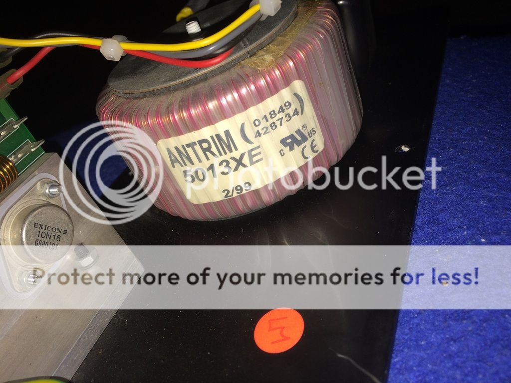
The UK version ("220-240vac 50-60 Hz") has a transformer that looks identical to yours and is also coded "5013 XE", so there doesn't seem to be an indication of current. My transformer secondary output is ±38.5 vac with the yellow & black centre taps. The only indication of current is in fuses F1 and F2 on the separate phases, which are both rated as "5A", which I presume are the same as yours and presumably offer protection through the rectifier at 10A.
You're perhaps more likely to get a better answer from someone who understands transformer ratings and alternating current mathematics rather than owners of these particular units. The transformer (disconnected) secondary coils are 1.3 ohms each, and the primary coil reading on my DVM is 23 ohm. My possibly dubious application of mathematics at 230vac gives 162.6Vrms and into 23 ohms rates as 7.A, 1.15 kW, but I don't know how transformer impedance might vary this result. At moderate listening volume the unit consumes approx 0.05kW
I'd be interested in your conclusion if you are successful.
- Home
- Amplifiers
- Solid State
- Anyone here own a Rel Sorm III sub?