Re: Re: MEASURING AND SPICE-MODELING A POWER TRANSFORMER
Thanks for chiming-in, Andy! And I'm glad you liked that link.
- Tom Gootee
http://www.fullnet.com/~tomg/index.html
-
andy_c said:
Thanks for that link, Tom. That's a really good article. He explains that stuff really well.
Well, I see Heinz has already posted something on this, but let me add a little bit also. I looked up the two-port parameters of an ideal transformer. The z and y matrices are undefined, but the h matrix is well defined. The parameters are:
h11=0
h12=1/N
h21=-1/N
h22=0
where N is the turns ratio.
Putting these into the two-port model with controlled sources gives the circuit pictured below.
Thanks for chiming-in, Andy! And I'm glad you liked that link.
- Tom Gootee
http://www.fullnet.com/~tomg/index.html
-
powerbecker said:Tom :
"Now, how can I get a measurement, without a special inductance meter?"
Tom,
take the primary voltage from a isolating variac and measure the primary current through the primary coil with a scope and a small shunt.
Rise the 60Hz voltage as long as the current looks like a sinus, or you reach the 110V.
From voltage and current you can calculate ZL.
Then subtract Rprim geometrically from ZL to get XL.
Together with the frequency (60Hz) you now can calculate Lp.
Andy,
thank´s for "dc-trafo", but please look to the left side :
2 voltage sources are switched parallel , E1 against V1 .
My stems from my old ewb5.1 simulator.
Heinz!
Heinz!,
Ah! (That "should" have been obvious, to me.) Thanks!
But, for some reason, I can't download the circuit image that you posted.
- Tom Gootee
http://www.fullnet.com/~tomg/index.html
-
Tom. "But, for some reason, I can't download the circuit image that you posted."
Tom,
same with me, I try 3 times to edit post attachment ...png...gif..nothing works!??
Don´t know what I do wrong
Tom,
same with me, I try 3 times to edit post attachment ...png...gif..nothing works!??
Don´t know what I do wrong
Andy,
I try a transient sim and get that:
**** --- Expanded Deck Component Count ---
E's 1
F's 1
R's 2
V's 2
tot: 6
--- Expanded Netist ---
* D:\DownLoadXP\idealtransformer-hb1.asc
e1 n001 0 out2 out1 2
f1 out1 out2 vtest 2
vtest in n001 0
r1 out2 out1 10
v1 in 0 2
r2 out1 0 100k
.tran 0 10m 0
.end
Fatal Error: Voltage source V1 is in a loop involving voltage source E1 and other
voltage sources and/or inductors making an over-defined circuit matrix.
You will need to correct the circuit or add some series resistance.****
powerbecker said:You will need to correct the circuit or add some series resistance.****
Ah, I see - thanks. I only did AC analysis, which worked okay. I'll try out the other matrix forms. Hopefully one of them will have a current source at the input.
Okay, here's a fix for that problem. Since I can't see the model in my head, I had to look up the circuit matrix again. This time, I used the G matrix. The controlled source model of the G matrix has a current source on the primary side. This makes it possible to model the mains as an ideal voltage source if needed. The G matrix equations look like:
I1 = g11E1 + g12I2
E2 = g21E1 + g22I2
For a turns ratio N, the G parameters of an ideal transformer are:
g11 = 0
g12 = -N
g21 = N
g22 = 0
The model ends up looking as shown in the picture below.
I1 = g11E1 + g12I2
E2 = g21E1 + g22I2
For a turns ratio N, the G parameters of an ideal transformer are:
g11 = 0
g12 = -N
g21 = N
g22 = 0
The model ends up looking as shown in the picture below.
Attachments
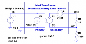
andy_c said:And here is the simulation file with the mains simulated as an ideal voltage source (not the best model, but the easiest). Transient works okay now, since there is no loop of voltage sources.
Thanks Andy,
and when you change the voltage source to the Sek and the RL to the Prim the same problem occur
Ohhh, and the same happens with my circuit when I exchanged load and source 😡
The simple solution : Add a resistor in series...and all 3 circuit went fine 🙂
Measure Primary Winding Inductance Of Power Transformer
Heinz!,
So, if I use a small resistance, Rs, in series with the primary winding, and get the variac up to about 110-115 VAC RMS and, using an oscilloscope, measure the 60 Hz sine voltage, Vp (zero-to-peak voltage), across the primary winding of the transformer-under-test, and measure Vs (zero-to-peak voltage) across the series resistor, then I should be able to calculate the approximate inductance of the primary winding, Lp, per the following:
Is = Vs (measured peak) / Rs
Rp = Vp (measured peak) / Is
Lp = Rp / (2*Pi*60)
Will that at least give an approximately-correct value for Lp?
OK. Yes, it does, apparently: I did, just now, do a "quick-and-dirty" spice simulation of such a measurement setup, with a 20H (single) inductor (with 20 Ohms internal series resistance added), and a 100 Ohm "current sense" resistor in series with the inductor, driven by an ideal voltage source (with no series resistance) of 164 v 0-P sine (approx 116 VAC RMS).
The simulation resulted in Is with 21.69 mA peaks and Vp with 163.97 V peaks.
The equations above would then give Rp = Vp / Is = 7559.7 Ohms and Lp = Rp / (2 x pi x 60) = 20.053 H.
I won't be able to measure the peak voltages that precisely, anyway. But I guess the calculated Lp that I get might be "close enough" to the actual Lp, under those operating conditions, for my modeling purposes.
If I use 100 Ohms for the current-sense resistance, I should be able to use a standard 1/4-Watt metal film type, since the resistor's power dissipation would be less than 24 mW average, for the setup described above at least.
"Just for fun", I pretended that I might be using a DMM (voltmeter), instead of an oscilloscope, to measure the AC voltages. (This obviously should work fine. But I just wanted to see the numbers come out right.) Assuming I had a meter that gave "true RMS" sinusoidal voltage measurements, I made LT-Spice display the voltages across the current-sense resistor (Vs) and across the primary winding (Vp), and used Ctrl-Left-Click on their plot labels to get LT-Spice to calculate their RMS values, giving Vprms = 115.95 VRMS and Vsrms = 1.5378 VRMS (Both were integrated only over the last 1.2 sec of a 2 sec simulation run). Using the equations above, but with the RMS values for Vs and Vp instead of the peak values, would give Isrms = Vsrms / Rs = 15.378 mA RMS, Rp = Vprms / Isrms = 7540 Ohms, and Lp = Rp / (2 x Pi x 60) = 20.00 H. So a "true-RMS" voltmeter should work as well as an oscilloscope, at least in cases where the equations above are a good-enough approximation, as long as it is valid to assume that the voltages are sinusoidal.
Does everything above look correct?
Thanks again, Heinz!, and andy_c!
P.S.:
Is there any problem with using a NON-isolated variac, OTHER than safety? I don't want to damage one of my scopes, for example. Maybe I'll just try my battery-powered DMM, instead, and calculate using the RMS voltages.
I have several variable mains transformers. But I don't _think_ they are isolating types, although I don't really _know_. I always assume they are non-isolating. If absolutely necessary, I could make an isolation transformer to put upstream from the variac, by using two identical back-to-back simple transformers. (But don't worry, in any case. I am _extremely_ safety-conscious, when using AC mains sources, and will set up all of the connections for "no-hands" operation, before plugging in the AC power cord, etc, and keep one hand in my pocket whenever power is on.)
Tom Gootee
http://www.fullnet.com/~tomg/index.html
-
powerbecker said:
Tom,
take the primary voltage from a isolating variac and measure the primary current through the primary coil with a scope and a small shunt.
Rise the 60Hz voltage as long as the current looks like a sinus, or you reach the 110V.
From voltage and current you can calculate ZL.
Then subtract Rprim geometrically from ZL to get XL.
Together with the frequency (60Hz) you now can calculate Lp.
Heinz!
Heinz!,
So, if I use a small resistance, Rs, in series with the primary winding, and get the variac up to about 110-115 VAC RMS and, using an oscilloscope, measure the 60 Hz sine voltage, Vp (zero-to-peak voltage), across the primary winding of the transformer-under-test, and measure Vs (zero-to-peak voltage) across the series resistor, then I should be able to calculate the approximate inductance of the primary winding, Lp, per the following:
Is = Vs (measured peak) / Rs
Rp = Vp (measured peak) / Is
Lp = Rp / (2*Pi*60)
Will that at least give an approximately-correct value for Lp?
OK. Yes, it does, apparently: I did, just now, do a "quick-and-dirty" spice simulation of such a measurement setup, with a 20H (single) inductor (with 20 Ohms internal series resistance added), and a 100 Ohm "current sense" resistor in series with the inductor, driven by an ideal voltage source (with no series resistance) of 164 v 0-P sine (approx 116 VAC RMS).
The simulation resulted in Is with 21.69 mA peaks and Vp with 163.97 V peaks.
The equations above would then give Rp = Vp / Is = 7559.7 Ohms and Lp = Rp / (2 x pi x 60) = 20.053 H.
I won't be able to measure the peak voltages that precisely, anyway. But I guess the calculated Lp that I get might be "close enough" to the actual Lp, under those operating conditions, for my modeling purposes.
If I use 100 Ohms for the current-sense resistance, I should be able to use a standard 1/4-Watt metal film type, since the resistor's power dissipation would be less than 24 mW average, for the setup described above at least.
"Just for fun", I pretended that I might be using a DMM (voltmeter), instead of an oscilloscope, to measure the AC voltages. (This obviously should work fine. But I just wanted to see the numbers come out right.) Assuming I had a meter that gave "true RMS" sinusoidal voltage measurements, I made LT-Spice display the voltages across the current-sense resistor (Vs) and across the primary winding (Vp), and used Ctrl-Left-Click on their plot labels to get LT-Spice to calculate their RMS values, giving Vprms = 115.95 VRMS and Vsrms = 1.5378 VRMS (Both were integrated only over the last 1.2 sec of a 2 sec simulation run). Using the equations above, but with the RMS values for Vs and Vp instead of the peak values, would give Isrms = Vsrms / Rs = 15.378 mA RMS, Rp = Vprms / Isrms = 7540 Ohms, and Lp = Rp / (2 x Pi x 60) = 20.00 H. So a "true-RMS" voltmeter should work as well as an oscilloscope, at least in cases where the equations above are a good-enough approximation, as long as it is valid to assume that the voltages are sinusoidal.
Does everything above look correct?
Thanks again, Heinz!, and andy_c!
P.S.:
Is there any problem with using a NON-isolated variac, OTHER than safety? I don't want to damage one of my scopes, for example. Maybe I'll just try my battery-powered DMM, instead, and calculate using the RMS voltages.
I have several variable mains transformers. But I don't _think_ they are isolating types, although I don't really _know_. I always assume they are non-isolating. If absolutely necessary, I could make an isolation transformer to put upstream from the variac, by using two identical back-to-back simple transformers. (But don't worry, in any case. I am _extremely_ safety-conscious, when using AC mains sources, and will set up all of the connections for "no-hands" operation, before plugging in the AC power cord, etc, and keep one hand in my pocket whenever power is on.)
Tom Gootee
http://www.fullnet.com/~tomg/index.html
-
andy_c said:And here is the simulation file with the mains simulated as an ideal voltage source (not the best model, but the easiest). Transient works okay now, since there is no loop of voltage sources.
andy_c,
Thanks for posting that ideal transformer model! I will definitely incorporate it into the transformer simulation model that I mentioned earlier in this thread.
Here is yet-another question: Since I would also like to be able to see some good approximation of how much current (for example) might be drawn from the mains, by a simulated power supply (PSU), especially during PSU startup, what sort of model of the AC mains supply might I want to use? And how much difference might it make, in the simulation results, to use something other than an ideal sine source for the mains' model?
I don't think I want to model the generating plant and all of the transformers and transmission lines, et al, from there to my power supply's location. 🙂
So I'm wondering what the next-better approximations of a mains model might be, AND whether it's even worth using a better mains model, or not.
I'm guessing that the most-minimal addition to the ideal voltage source model would be a series resistance. How much resistance, I don't know, yet. And then, I suppose, a series inductance and a shunt capacitance might need to be added. If I go back to my transmission line theory textbook, and then make some measurements and/or calculations, I might be able to come up with a lumped-component model for the distributed effects of the transmission line, power cord, etc. But surely there must already be a reasonable and simple "typical" model existing. (I must confess that I haven't done any searches for one, yet. Sorry if the answer is already widely-available and well-known.)
However, as I also mentioned above, the first question should probably be, "Will a better mains model make enough difference to be worth worrying about it?".
Thanks again for all of your help, so far, Andy!
Tom Gootee
http://www.fullnet.com/~tomg/index.html
-
Re: Measure Primary Winding Inductance Of Power Transformer
Tom,
all you write looks correct, thank you!
BTW, I found that a 2.2kVA poweramp for 230V main simulation from a client use optional as main resistance a series connection of 0.4 E with 800 uH in the output.
Heinz!
Tom,
all you write looks correct, thank you!
BTW, I found that a 2.2kVA poweramp for 230V main simulation from a client use optional as main resistance a series connection of 0.4 E with 800 uH in the output.
Heinz!
gootee said:Since I would also like to be able to see some good approximation of how much current (for example) might be drawn from the mains, by a simulated power supply (PSU), especially during PSU startup, what sort of model of the AC mains supply might I want to use? And how much difference might it make, in the simulation results, to use something other than an ideal sine source for the mains' model?
I don't think I want to model the generating plant and all of the transformers and transmission lines, et al, from there to my power supply's location. 🙂
Boy, you got me on that one!
 I haven't a clue! My Black & Decker house wiring book says that the transformer at the utility pole steps the voltage down from 10 kV to 120 V in the U.S. So maybe one can neglect the resistance at this point? Dunno. But this thread has come at a very good time for me, as I'll be getting the transformers for my power amp in a week or so I hope.
Here's what I've been doing, but I don't know if it will help. I'll be getting a couple of Avel-Lindberg 1 kVA transformers that I'll use together as the equivalent of a single 2 kVA transformer. They give regulation data of 3.8 percent for this model. This assumes a resistive load with sinusoidal current. Using the definition of regulation, I compute the open-circuit voltage looking back into the secondary. Then the equivalent series resistance (reflected to the secondary) can be calculated. This works out to a little less than 0.2 Ohms. To double check this, one can take the rated secondary RMS current squared and multiply it by this resistance. This comes out very close to what they specify as their copper losses (taking into account two secondaries). So I guess the question becomes, "If you take the mains impedance and reflect it to the secondary of the transformer, what fraction of the transformer's equivalent secondary impedance is it?". I suppose this becomes more and more important as the VA rating of the transformer increases, with diminishing returns likely.
At any rate, I just model the secondary as a voltage source with this 0.2 Ohm resistance in series with it. I have diode models that have been fit to the curves of typical 35A bridge rectifier diodes. Using B-source current sources with half-wave rectified currents to simulate the power amp load on the power supply, I look to see what effect the transformer has on the sag of the DC voltage as the amp is tested under load. It's quite a bit. I also use LTSpice to compute the RMS value of the pulsed secondary current to determine the required VA rating of the transformer. So I know what the instantaneous secondary current will look like, under the assumption of testing the amp under full power with a sine wave and 4 Ohm load. Then I'll add the transformer model and copy what you end up doing with your transformer inductance measurements. I hope to use this info to calculate RC snubbers to use across the bridge rectifier diodes to minimize RF generation.
So I'm wondering what the next-better approximations of a mains model might be, AND whether it's even worth using a better mains model, or not.
Well, I guess if the transformer losses dominate, that makes the problem a lot easier. But I don't know what kind of circuit you're working with.
Re: Re: Measure Primary Winding Inductance Of Power Transformer
Heinz!,
Thanks!
And thanks for the information about using 0.4 Ohms in series with 800 uH as a model for a mains impedance. I'll try it in my PSU simulation model.
- Tom Gootee
http://www.fullnet.com/~tomg/index.html
-
powerbecker said:
Tom,
all you write looks correct, thank you!
BTW, I found that a 2.2kVA poweramp for 230V main simulation from a client use optional as main resistance a series connection of 0.4 E with 800 uH in the output.
Heinz!
Heinz!,
Thanks!
And thanks for the information about using 0.4 Ohms in series with 800 uH as a model for a mains impedance. I'll try it in my PSU simulation model.
- Tom Gootee
http://www.fullnet.com/~tomg/index.html
-
POWER TRANSFORMER LT-SPICE MODEL (ATTACHED)
I finally hauled-out a variac and measured the inductances of my little 56VA transformer (Triad Magnetics VPP36-1560 / Hammond 183K36). Actually, for the primary, I didn't even use the variac.
I connected a 99.13 Ohms 1/4-Watt metal film resistor (100 Ohms nominal 1% Resistor, measured as 99.22 Ohms minus 0.09 Ohms measured with probes shorted) in series with the primary, using a bare-ended mains cord and some heavy alligator-clip jumpers. I plugged in the mains cord and measured 6.075 VRMS across the resistor and 120.8 VRMS across the primary winding's terminals, using my DMM.
Using the equations given in Post #29 of this thread, I calculated the primary's inductance to be 5.229 H.
Then I got the idea that I should do the same sort of measurement for the secondary winding's inductance, even though that measurement is not needed for the model that I was measuring parameters for. Not having planned for that, and apparently not thinking very well, I initially left the 100 Ohm resistor in place.
I moved the AC connection to the secondary and connected it to the variac, instead of directly to the AC mains, and then measured the secondary's voltage as I cranked-up the variac, trying to get it to the 22.2 VRMS that I had measured when there was 120 VRMS on the primary. As I was doing that, the poor little 100-Ohm 1/4-Watt resistor began smoking and turned black. 🙂
I was too lazy to go and look for a properly-sized power resistor. So I used a 470 Ohm 2 Watt metal film resistor that I happened to have next to me. I applied power again and raised the secondary voltage to about 20.49 VRMS and noticed that the 470 Ohms 2W resistor had melted through the plastic foam-like packaging sheet that it had been lying on. I used it, anyway, but could only leave the power on for about 2 seconds at a time, for measurements. With that setup, I measured Vs across the resistor as 61.36 VRMS, and Vsecondary as 20.49 VRMS. Using the same equations, from Post #29, I calculated Ls to be 0.4104 H.
Getting back to the task at hand:
In order to use the equations in Post #14 of this thread, to derive the parameters for the Spice transformer model's circuit that is given in the appnote, http://www.onsemi.com/pub/Collateral/AN1679-D.PDF , I also needed to measure the primary winding's inductance with the secondary SHORTED.
It was obvious that I didn't want to apply 120 VRMS to the primary, with the secondary shorted. But I thought that perhaps I could start at 0 V and increase the variac's voltage until the secondary's current reached its rated value, using a DMM in current-measuring mode to connect the secondary's terminals.
I tried to do that, with a 99.09 Ohm resistor in series with the primary. But before the secondary's current got much above zero, the resistor started to smoke a little bit and I cut the power.
So I then decided to settle for increasing the variac's voltage until the resistor had approximately the same voltage that it had had when I had done the measurements with the secondary NOT shorted. (I am not sure if this was sufficient, or not. Comments would be welcome.)
So, I shorted the secondary with a jumper and raised the variac's voltage until the voltage across the resistor was 5.877 VRMS, and then measured the voltage across the primary winding to be 3.061 VRMS. From those measurements, I calculated Lpsshort = 0.5037 H (for Step 3 in Post #14 of this thread).
Here are the parameters for the transformer model, recalculated based on these new measurements, using Steps 1 through 8 on page 4 of the appnote referenced above, for the model's schematic in Figure 8 on Page 4 of the appnote:
N = 5.464
Lpsopen = 5.229 H
Lpsshort = 0.5037 H
k = 0.9506
L11 = 0.2583 H
L12 = 0.008652 H
Lm = 4.971 H
Rp = 20.85 Ohms
Rs = 0.73 Ohms
The LT-Spice Power Transformer and AC Mains model file is attached. Remove the .TXT from the filename, to use it with LT-Spice.
In this LT-Spice transformer model, if the measured tranformer parameters are entered, all of the other parameters are automatically calculated.
Thanks again, andy_c and powerbecker!
- Tom Gootee
http://www.fullnet.com/~tomg/index.html
-
Attachments
Andy,
Thanks for taking so much time to respond.
In the LT-Spice transformer model that I attached to my previous post, I included a tentative AC Mains model, using Heinz's kindly-provided example of having 0.4 Ohms in series with 800 uH to model the mains.
I suppose that if only the mains WIRING were to be considered, it would be trivial to estimate the series resistance and inductance for a given length of a given gauge of wire, maybe using some "average" length for the wire between the power supply and the pole transformer. I 've no idea, though, really, and haven't done even a rough estimate to see how it might compare to the 0.4 Ohms/800 uH.
And, although I didn't put it into the model I posted, this way, I assume that both the hot and neutral should have the same series inductance and resistance (assuming they're made with the same type of wire).
By the way, just to let you know: I did have to tweak your ideal transformer model, ever-so-slightly: I needed to add another large resistance to ground, so that both windings have that. Otherwise, there was some definite "weirdness" possible, with the voltages on either side of the ideal mains source, especially when the transformer model was wrapped around it, and higher voltages and currents were present, and depending on where grounds were connected, etc. It even varied very significantly with the spice timestep size. There was lots of distortion and noise, huge spikes, oscillation, etc, sometimes, and possible extreme asymmetry between the two sides of the ideal AC Mains voltage source. It seemed to only affect the voltages, not the currents, around the AC source, and never affected the output voltages or currents at all. I never did understand what caused it, or what it even was. I almost have to assume that it was some math/solver problem, inside spice. But that's all gone, now, I hope. And, I also inverted your definition of the turns ratio, N, to match what was used in the appnote that I was basing my transformer model on.
It's great to finally read a few details of what someone else is doing, with power supply modeling. Thanks! And it's nice to see that your testing methodologies and goals bear at least some resemblance to mine.
The supply for which I am attempting to improve the LT-Spice model will be used to power a test instrument (a small curve tracer), which has a small (30W) audio-frequency-range power amplifier as one of its major sub-systems (It's an LM1875 chipamp-based power amp, actually, but with a high-precision very-wide-dynamic-range AGC, and a high-precision DC Servo, et al, to try to provide precise, accurate, stable, user-selectable, calibrated output amplitudes, for several types of periodic signals that can be used to drive the device-under-test, at frequencies from 60 Hz to 22 kHz, with up to about 1.5-Amp peak currents.).
I too have been interested in worst-case startup behavior of the power supply. But, lately, I am ALSO becoming very interested in minimizing the disturbances on the power supply rails that are caused by the power amp sub-system (for example), since certain other sub-systems would like to have the power rails be as quiet as possible.
To simulate a dynamic load that approximates the power amp in my unit, I have just used the OPA541E chipamp model from Texas Instruments' website, since there seem to be no spice models for National's chipamps.
My power supply's output eventually gets split, to form equal + and - rails and a virtual ground. (Interestingly, maybe, the "railsplitter" is made using another LM1875, somewhat similarly to how it is shown in the LM675 datasheet at national.com . It works great for up to a few amps.) So, for example, I can set up an OPA541 across the rails at the PSU's output, and configure it as a voltage follower (or whatever) and have it pump +/- 15v (almost-)square waves into, say, 10 Ohms, which approximates, fairly well, a worst-case (or worse) load scenario that my real power amp sub-system might present to the power supply.
With board-to-board wiring impedances, etc, also modeled, I was getting 30 mV (but in some cases up to 150+ mV p-p) fluctuations in the +/-17.5V power rails, and, unfortunately, also in the virtual ground's rail, probably mostly due to the power amp's current consumption profiles, when driving worst-case-current loads with fast edges, as in the example mentioned above. The rail fluctuations in the simulation results pretty-closely matched measured results from a working prototype. And that was when it was basically as good as I could possibly design it to behave, while it was extremely easy to make it much, much worse.
I could have gone to each of the 10 or more other places where the power and ground rails enter another PCB, and added additional RC filtering, or added more actual regulation, etc, at least for the more-sensitive circuits. But I thought that it MIGHT be much better if I could attack the problem at its source, first at least. I also didn't have much PCB space left, for additional regulators, filtering, etc.
I eventually discovered, using a little thought, and a whole lot of trial and error, that adding relatively small series chokes (inductors), which are roughly from 1X to 1.5X the size of a standard 1/4 Watt resistor, as well as a little more capacitance (as it turned out, although that was not causing the biggest effect, by far; basically just for "tuning"), possibly in parallel with a small resistor (although, that was NOT better for the amp board's chokes), RIGHT at the point where the power rails met the power amp subsystem, was _incredibly_ effective. In simulations, at least, the main PS rails' and virtual ground's fluctuations were then reduced to just a few tens of uV p-p, for the worst case. (I just recently did this, and haven't yet tested it in a prototype.) In almost the same way, I also solved similar problems that were being caused by an LM311 comparator that had to bounce almost from rail to rail while driving an external coax connection, and by an opamp that also functioned as a comparator (for making extremely-flat-topped square waves to integrate into extremely-linearly-sloped triangle and sawtooth waveforms).
I suppose that all might fall under the heading "load regulation", or maybe "load isolation". But I don't remember ever seeing a good discussion of it, before. Maybe I haven't been looking in the right places. But I had always been rather disappointed, seeing what happened when a dynamic load was connected to a power supply that had been carefully tweaked to have almost zero output ripple, with a resistive load (and also the ones I had designed to also be able to handle capacitive loads, well).
Regarding the PSU "sagging" effects with various load conditions, and especially during PSU startup: Using the new (to me) spice transformer model, that I attached to my previous post, the difference in my PSU's startup performance, compared to only modeling the secondaries as ideal AC sources with series resistances, is _very_ significant. I don't like what I've seen, so far. But maybe that's mostly because it's different-enough from what the simpler models had led me to believe, that it negates parts of some newer design work that I had already thought was "done".
In my PSU's case, at least, the "sagging" effects are quite pronounced, at least during startup (which is about all I've looked at, so far), delaying startup much more than I thought, while the input capacitor charges, and the boost-mode SMPS that follows sucks huge currents in through its input inductor, etc. There seems to be a bit less power available than I thought, during startup. On the bright side, the huge startup currents that the input capacitor and SMPS were sucking in are now not looking quite as large as I thought they were. Unfortunately, that might also mean that I wasted my time, while coming up with a startup-current-limiting circuit.
One "possible" problem, with MY model, which might even explain or change the simulated PSU performance differences I just mentioned: When I measured the primary's inductance with the secondary SHORTED, I didn't take the time to alter the setup so I could get voltages that might have been high-enough to better-match actual working conditions, or at least high-enough to get a better measurement for the purposes of the model. At least I THINK that that might be a problem. I really have no idea what voltage I should have been aiming for. IIRC, I only put about 3V across the primary, when the secondary was shorted. I also didn't measure the secondary's current, to see if it seemed "reasonable". Do you have any idea what voltage I should have tried to use across the primary, when the secondary was shorted, or maybe some other approach to getting a reasonable measurement? As I mentioned in the post in which I described my measuring process, I had thought that I might be able to increase the primary voltage until the secondary's current was near its maximum rating, or at least to some realistic operating point. If more would be better, I can figure out how to get it done. (I suppose I should simply TRY it, and see how much it affects the model's performance.)
Sorry to be so long-winded, again. Sometimes, when I feel that I don't really know what I'm doing, I try to give lots of detail, hoping someone might see an error, or be able to suggest a better approach, etc. I'm always wanting to learn more from those who know more.
- Tom Gootee
http://www/fullnet.com/~tomg/index.html
-
Hi Tom,
Wow, that sounds like quite a circuit you're working on.
I saw your simulation file. It looks like the 1000 Meg resistors you added are just standard SPICE procedure for preventing floating nodes. Or was there something else needed? If so, give me a holler so I know I'll need to add them too.
Back in the early '90s I used to work on radar receivers that had multiple identical channels and high gain. We'd always put a choke at the power supply pin of every RF amp. Depending on the frequency the receiver operated at, we'd often be able to choose the choke value so its parallel resonant frequency was near the middle or high end of the operating bandwidth. There's nothing like a high series impedance in the power supply at the operating frequency for preventing crosstalk between channels and between amps in the same channel. Also, we had some circuits with gain over 70 dB at around 600 MHz. If a decent sized AC signal got on the power supply and was picked up by the amplifier all the way back at the input, boy did some strange stuff happen. So it doesn't surprise me that you're seeing improvements with chokes in the supply lines. The high series impedance of the choke in the transient condition can really do wonders for preventing one circuit from interacting with another.
Regarding the transformer with shorted secondary, here's one thing I thought of. Suppose you loaded the secondary with a small resistor and grounded one side of it. Then you could look at the voltage on a scope. By slowly bringing the variac up, maybe you could find a secondary current that was just below the point where distortion could be seen on this voltage. From the turns ratio, you'd also know the primary current. Then, knowing the series primary resistor and assuming almost zero Ohms on the primary with secondary shorted, you could figure out what the variac voltage should be. Just a thought - I'm not experienced with power magnetics, so I hope to use this thread as a learning tool. That article by the guy from OnSemi was a big step in that direction.
***So I then decided to settle for increasing the variac's voltage until the resistor had approximately the same voltage that it had had when I had done the measurements with the secondary NOT shorted. (I am not sure if this was sufficient, or not. Comments would be welcome.)
So, I shorted the secondary with a jumper and raised the variac's voltage until the voltage across the resistor was 5.877 VRMS, and then measured the voltage across the primary winding to be 3.061 VRMS. From those measurements, I calculated Lpsshort = 0.5037 H (for Step 3 in Post #14 of this thread).***
Tom, this is OK, for this test (leakage inductance) it´s only
important that the primär voltage is small.
About 5% from the nominal value is good to avoid influence from the magnetized iron.
I´m a little bit surprised that the leakage inductance is 10% from Lprim...that is unsual high.
Has the bobbin separate chambers?
Tom, you should reduce the "mains impedance" because it´s calculated for a 230V socket!
Heinz!
powerbecker said:***So I then decided to settle for increasing the variac's voltage until the resistor had approximately the same voltage that it had had when I had done the measurements with the secondary NOT shorted. (I am not sure if this was sufficient, or not. Comments would be welcome.)
So, I shorted the secondary with a jumper and raised the variac's voltage until the voltage across the resistor was 5.877 VRMS, and then measured the voltage across the primary winding to be 3.061 VRMS. From those measurements, I calculated Lpsshort = 0.5037 H (for Step 3 in Post #14 of this thread).***
Tom, this is OK, for this test (leakage inductance) it´s only
important that the primär voltage is small.
Thanks, Heinz!. Next time I do such measurements, I will try to be at least a little smarter about it, and take at least three data points, so I can see the measurements' variation versus operating point.
About 5% from the nominal value is good to avoid influence from the magnetized iron.
It sounds like you mean that the primary's test-voltage should be something like .05 X nominal operating voltage. Is that correct? (I ask because, normally, I would think that "5% from..." would mean "0.95 X...".)
I´m a little bit surprised that the leakage inductance is 10% from Lprim...that is unsual high.
Has the bobbin separate chambers?
It is a "split bobbin" type of construction, advertised as follows:
"Low profile, split bobbin with top shroud design."
"Dual winding secondaries, non-concentrically wound."
"Low primary to secondary coupling - no electrostatic shield required."
Here's a thought: I was purposely trying to get a model for only ONE of the dual secondaries and one of the dual primaries. So I only shorted ONE of the secondaries, when trying to measure the leakage inductance of the one primary, and only applied the voltage to the one primary; the one with pins opposite to those of the secondary I shorted. I did it that way because it "appeared" (looking at the bottom of the transformer, where the pins are, and the bobbins are visible) that each bobbin was for one primary and one secondary, only.
But maybe I was completely wrong! And it seems that if there was _any_ coupling between the one primary that I tried to measure, and the secondary that I did not short, then the inductance would measure too high. Is that correct?
I don't know how "good" these transformers are, really. I used them because their SIZE was right for my enclosure, and because they are PCB-mounted, and also because I can have the primaries switchable to run from 115v or 230v. They're cheap, too. Their current price at http://www.mouser.com is $21.80/1 or $174.40/10.
Tom, you should reduce the "mains impedance" because it´s calculated for a 230V socket!
Oops! Will do. Thanks!
- Tom Gootee
http://www.fullnet.com/~tomg/index.html
-
andy_c said:Hi Tom,
Wow, that sounds like quite a circuit you're working on.
Well, it's been "evolving" for a long time. I would hate to admit how much time I've spent, on parts of it. But I've rationalized it as a learning experience. 🙂 Even though I was, originally, an EE, I don't have the lifetime of work-experience with circuits, that a lot of EEs have, because I did mostly (non-EE) software, for decades, and, actually, did mostly control-theory stuff even when I WAS doing EE work, way back when. I started dabbling again only less than ten years ago, but didn't get serious about it until about two to three years ago. However, I figure I've put in at least five or six man-years, since then. 🙂
I saw your simulation file. It looks like the 1000 Meg resistors you added are just standard SPICE procedure for preventing floating nodes. Or was there something else needed? If so, give me a holler so I know I'll need to add them too.
Yes, the extra 1000Meg resistor on the primary side is the only thing that needed to be added. But it wasn't a "floating nodes" problem, necessarily (no error messages like that, at least). Try removing it, and having no other grounds on the primary side, and plot the voltages on both of the primary inputs. Then see what happens if you copy the ac mains resistor and inductor and have them on both sides of the ac source. Then reduce the timestep to .001 amd look at the primary's input voltages again, even zooming in on them. And then look at the voltage across the load.
OH! I just-now did all of that, but then changed the plot of V(pri_1a) to V(pri_1a) - V(pri_1b) and got a good sinusoid! So, it looks like it technically "works", either way (i.e. with or without the 1000Meg on the primary side), especially as far as the output is concerned. But without the 1000Meg to gnd, for the primary side, it's "appearing" in a "differential mode". That should probably make perfect sense, if I thought about it.
Back in the early '90s I used to work on radar receivers that had multiple identical channels and high gain. We'd always put a choke at the power supply pin of every RF amp. Depending on the frequency the receiver operated at, we'd often be able to choose the choke value so its parallel resonant frequency was near the middle or high end of the operating bandwidth. There's nothing like a high series impedance in the power supply at the operating frequency for preventing crosstalk between channels and between amps in the same channel. Also, we had some circuits with gain over 70 dB at around 600 MHz. If a decent sized AC signal got on the power supply and was picked up by the amplifier all the way back at the input, boy did some strange stuff happen. So it doesn't surprise me that you're seeing improvements with chokes in the supply lines. The high series impedance of the choke in the transient condition can really do wonders for preventing one circuit from interacting with another.
Perfect! Now I wish I'd "just asked".
That sounds like it must have been some fun stuff, that you were doing!
I worked on defense aerospace stuff, back when I was a new EE, in the early 1980s. I sometimes wish I'd stuck with it, instead of striking out on my own, mainly because it was so great to work with the other people who were there. I've been working alone, for years now, and have to watch out for "cabin fever", heheh.
Regarding the transformer with shorted secondary, here's one thing I thought of. Suppose you loaded the secondary with a small resistor and grounded one side of it. Then you could look at the voltage on a scope. By slowly bringing the variac up, maybe you could find a secondary current that was just below the point where distortion could be seen on this voltage. From the turns ratio, you'd also know the primary current. Then, knowing the series primary resistor and assuming almost zero Ohms on the primary with secondary shorted, you could figure out what the variac voltage should be. Just a thought - I'm not experienced with power magnetics, so I hope to use this thread as a learning tool. That article by the guy from OnSemi was a big step in that direction.
Thanks, Andy. I can try that, too. But as I said in my answer to Heinz, last night, I think I might have simply goofed-up the whole thing:
My split-bobbin transformer has dual primaries and dual secondaries. I was under the impression that I could treat them as two separate single-pri/single-sec transformers, for modeling (and measuring) purposes. But now I'm not sure if it can be modeled well, that way, and, even if so, I don't know if my measurement methods were valid (probably not), especially for the leakage inductance, since I only shorted ONE of the secondaries, to measure what I thought was the "corresponding" primary.
At this point, I can't say that I even know whether there IS a valid way to measure them, "separately". But I'm just going to try it again, at least, and see what I get for one primary with both secondaries shorted. The comparison with the previous result should be enlightening.
While I've got the measurement setup in place, again, I'll also take measurements for both primaries together, in series and in parallel, with both secondaries shorted.
I think that I'll also do all of the other measurements again, for the two cases with 1) paralleled secondaries and paralleled primaries, and 2) paralleled secondaries and series primaries. I will also have to go back and see if a different model (and probably some extra measurements) will be needed, for either or both of those cases, rather than the simple two-winding model. I guess that I might have to use the three-winding model in the referenced appnote, at least for the series-primaries case. I kind-of hope that I don't have to try to find or develop a four-winding model. (Or maybe I should just use a transformer that has only one secondary.)
I only wanted to treat them as two separate transformers so I could more-easily simulate different primary and secondary configurations. But, for this project, all I truly need are two models, both with the secondaries in parallel, and one with the primaries in parallel and one with the primaries in series.
I'm sorry if I have wasted other peoples' time, by not clearly-defining my transformer configuration, versus how I thought I could model it. But, by considering only the two-winding case, I have at least learned some of the basics.
One thing that I should probably also think about, right about now, is finding out if there are any easy-enough ways to VALIDATE any resulting transformer models. I haven't given it any thought, yet. So don't laugh, if the answers are obvious. 🙂 I guess the trivial case would be to simulate the original measurement methods and make sure the model gives close to the same results.
But I'd like to also validate things like the transient response for load changes, and try to get an idea of whether or not the startup behavior is modeled well-enough. I guess that might be difficult, without a storage scope. I'll have to check to see if I still have a working one, around here somewhere. I do also have some working analog X-Y plotters, and some strip-chart recorders. I think that one of the HP X-Y flatbed plotters that still works is quite fast, and might be able to stretch some fraction of a second of a signal across 15 inches or so of paper. I'll have to check the strip-chart recorders' speeds, too. I do have "a bunch" of old scopes, here, left over from when I used to buy and resell surplus equipment. And there's probably a storage scope among them. And I have an old Tek 564B that needs a cazapitor replaced, somewhere. I guess that, either way, though, it'd be something like a whole day spent, to get a working setup put into place, unless I got extremely lucky. More decisions to make... 🙁
Thanks again, Andy! I'll do some more research and try to sort all of this out, and report back.
- Tom Gootee
http://www.fullnet.com/~tomg/index.html
-
gootee said:
Thanks, Heinz!. Next time I do such measurements, I will try to be at least a little smarter about it, and take at least three data points, so I can see the measurements' variation versus operating point.
It sounds like you mean that the primary's test-voltage should be something like .05 X nominal operating voltage. Is that correct? (I ask because, normally, I would think that "5% from..." would mean "0.95 X...".)
It is a "split bobbin" type of construction, advertised as follows:
"Low profile, split bobbin with top shroud design."
"Dual winding secondaries, non-concentrically wound."
"Low primary to secondary coupling - no electrostatic shield required."
Here's a thought: I was purposely trying to get a model for only ONE of the dual secondaries and one of the dual primaries. So I only shorted ONE of the secondaries, when trying to measure the leakage inductance of the one primary, and only applied the voltage to the one primary; the one with pins opposite to those of the secondary I shorted. I did it that way because it "appeared" (looking at the bottom of the transformer, where the pins are, and the bobbins are visible) that each bobbin was for one primary and one secondary, only.
But maybe I was completely wrong! And it seems that if there was _any_ coupling between the one primary that I tried to measure, and the secondary that I did not short, then the inductance would measure too high. Is that correct?
I don't know how "good" these transformers are, really. I used them because their SIZE was right for my enclosure, and because they are PCB-mounted, and also because I can have the primaries switchable to run from 115v or 230v. They're cheap, too. Their current price at http://www.mouser.com is $21.80/1 or $174.40/10.
Oops! Will do. Thanks!
- Tom Gootee
http://www.fullnet.com/~tomg/index.html
-
Tom, yes 5% from nominal voltage means :
100% = 120V --> 5% = 6V...
and for valid results it is necessary to use ALL windings on the core !
Much success,
Heinz!
- Status
- Not open for further replies.
- Home
- Amplifiers
- Power Supplies
- Anyone have SPICE models for PSU Toroidal Xfmr ??