Hi,
I'm curious to simulate the typical full wave recitifier in a power amps PSU. Does anyone have a SPICe model for a typical toroidal transformer used in a solid state power amp?
Failing that I could devise one but have no idea of the values involved. Anyone know for a given VA rating what the primary, secondary and mutual inductances will be along with the winding resistances and parasitic capacitances?
Yours hopefully
13th Duke of Wymbourne
I don't know if you looked at Duncan's PSU designer (sorry, no link handy, but you should be able to find it easily with a search). It may do what you're looking for. Certainly, it is sufficient for designing most power supplies for audio amplifiers.
-Won
-Won
Rod Elliot's Linear Power Supply Design article describes how to model transformers - I don't know if it'll be accurate enough for what you want, though.
I think the gist of it is to have an AC voltage source with a series resistance (which works for pretty much any real-life transformer, anyway).
I think the gist of it is to have an AC voltage source with a series resistance (which works for pretty much any real-life transformer, anyway).
13DoW said:
Does anyone have a SPICe model
for a typical toroidal transformer
used in a solid state power amp?
Yours hopefully
13th Duke of Wymbourne
Anyone have SPICE models for PSU Toroidal Xfmr ??
Yes, real good topic ........
I want also to know howto simulate a 'close to real transformer'.
Using ideal voltage sources in spice models make me feel a bit sick 🙄
When doing good sims, we want to come as close to reality as possible.
If not, we may fool ourselves and others too - with imaginary results of sims.
***************************
Anybody?
1. How can I use my simulator to set up a somewhat credible transformer?
2. In my power amplifiers, I have used 'virtual transformer' followed by rectifier.
But I am not sure how to set the parameters for this trafo.
I am sure someone could share some knowledge in this.
Those guys into Class-D and those into Switching Supplies must know this!!
Regards
lineup
There are quite a few examples of spice transformer simulations, in the Files section of the LTSpice group, at http://www.yahoogroups.com .
First, download the file there that has a descriptive list of all of the files. It's very useful for doing text searches, in order to find all of the relevant files.
There are both linear and non-linear transformer models, there.
There is even a complete spice simulation model of a Fischer 500C tube amp, there, including the transformers.
I also remember seeing a model that simulated both the electric and magnetic properties of transformers, using electric analogs of the magnetic portions.
And there is also a small library (from Intusoft, IIRC) with certain real inductor cores' non-linear models, with settable parameters for # turns, etc. (Not transformers, per se, but thought I'd mention it; very good for certain inductor models, maybe.)
But I don't remember seeing, in the transformer-specific files at least, any realistic sets of parameters for any typical solid-state amp's power transformer, although there might be some in some files that are about simulating larger systems, rather than only a transformer.
The "basics" (and some not-so-basics) all appear to be there, though, such that you would only need to know the parameters to use for the transformer you want to simulate.
I'd be very interested in seeing any spice power transformer models that people develop.
Attention, manufacturers of all types of electronic components: If you provide spice models for your products, we will be more likely to design with your products.
- Tom Gootee
http://www.fullnet.com/~tomg/index.html
-
THIS thread (linked below) seems quite relevant:
http://www.diyaudio.com/forums/showthread.php?s=&postid=1024017&highlight=#post1024017
That being said, I still tried using a spice transformer model with two coupled inductors, per the following thread (with parameters said to be reasonable for a 220VA 24x24 transformer, in the post linked below):
http://www.diyaudio.com/forums/showthread.php?s=&postid=1086760&highlight=#post1086760
i.e. I put two inductors onto my LTSpice schematic, checking the boxes to "Show Phase Dot", rotated and mirrored them as needed so they "looked like" a transformer (not strictly necessary), set the inductance of the primary to 10H and secondary to 0.45H, set the series resistance of the primary to 6.4 Ohms and the secondary to 1.5 Ohms. I used the .op button to create the line "k1 L1 L2 1" on the schematic, to "couple" the two inductors to make them behave like a transformer. Finally, I connected an ideal AC voltage source across the primary, with voltage = 120 X 1.414 = 169.68 (for USA's 120VAC case). I had to connect the negative side of the voltage source, and the "bottom" of the primary's inductor, to ground, so LTSPice wouldn't complain about "floating nodes". The secondary's output into 10K Ohms was 36v 0-p (36/1.414 = 25.45 VAC).
Test conditions:
First, I arbitrarily changed the secondary's inductance until the secondary voltage was 18VAC (18 X 1.414 = 25.45 V 0-P, with L2=0.2258H), since I have an existing PSU's spice model that runs on that voltage (36vct xfmr with paralleled dual secondaries). I know that that's probably not correct. But I just wanted to run some kind of test-simulation, immediately.
Then I connected the new spice transformer model to the input of the existing LTSpice model of a power supply that I designed and of which several have been built and tested, which includes models of: a rectifier bridge, a mosfet-based "soft-start" inrush current limiter, then 12000uF/.035 ESR (and other smaller) input filter caps with 2.2k bleeder resistance in series with LED "power on" indicator, followed by an LT1270A-based switchmode boost converter (SMPS, 20V nominal DC in/38VDC out), LR/C output filter (37vdc out), LT1084-based post-regulator (35VDC out), LM1875-based rail-splitter (+/-17.5vdc output rails with new virtual ground), LT1086-5 fixed 5V regulator (for extra 5Vdc rail for CMOS stuff), and attached a model of a power chipamp voltage-follower to the +/-17.5v rails, that was pumping +/-15V square waves into a 10 Ohm resistor, which I had used previously to test this PSU model. All inductors and capacitors also have realistic ESR (equivalent series resistance) added. I used the OP541E model from http://www.ti.com , to simulate the LM1875.
The transformer model seems to work well-enough, although, as Eva pointed out in the first-linked thread, above, NOW the AC Mains still aren't modeled.
However, at least I was able to see a difference in the primary winding's current drawn from the AC Mains, during startup, with and without the soft-start circuit. (BUT, how accurately it matches reality, I haven't yet determined.)
Note that almost ALL of the startup waveforms are MUCH different than when using an ideal AC voltage source to model only the transformer's secondary! And they are slightly different than when using an ideal AC source with a series resistance to model only the secondary.
- Tom Gootee
http://www.fullnet.com/~tomg/index.html
-
Ain't that many transformer manufacturers publishing decent specs. Most manufacturers list only VA rating and maybe mounting configuration, diameter and weight. Why not primary/secondary inductances, winding resistances and parallel capacitances. It's a damn shame.
I have used following to simulate 250VA 230-48 transformer:
Lp = 10H, series resistance 6,4 ohms
Ls = 0,45H, series resistance 1,5 ohms.
The resistances are real measured values. The primary inductance was guessed based on some article I read yours ago (I do not have an inductance meter) and the secondary inductance is selected to give the specified voltage to moderate load.
My point is to say that if you know some specs of the actual part you can at least make a decent model which, in simple applications, works pretty well. I have noted that the model tends to sag pretty early, though. Something like this is also a highly simplifed version of an actual transformer and one has to take that in account when running simulations. For example, I wouldn't dare to trust into its accuracy in SMPS sims.
Edit: Inspired by this thread I did a quick search on primary inductances... again with mediocre luck. Fortunately, Rod Elliott's site (http://sound.westhost.com/xfmr2.htm) lists some measurements, which seems to indicate I estimated the inductance to be too low when I came up with the described model. 40 - 50H could be a more realistic value for a 250VA toroid.
teemuk,
Thanks. Yours were the numbers I was using, above, in my first transformer modeling attempt.
I'm just now starting to try to model transformers in LTSpice. But finding reasonable parameters for the models has been the biggest hurdle, so far. Using better (i.e. non-linear) models would probably help, too. But maybe/probably that would make finding the parameters even more difficult. If I pursue this much further, I'll probably have to try to figure out how to actually measure everything I need.
Here is an interesting thread segment that I just found (post #7, by I_Forgot, mainly):
http://www.diyaudio.com/forums/showthread.php?s=&postid=1132802&highlight=#post1132802
I haven't quite gotten my head around setting up the non-linear inductor models, yet. But there are also further examples in the Files section of the LT-Spice group at yahoogroups.com .
There is also some excellent discussion of transformers in the sci.electronics groups, at http://groups.google.com , which also now has the searchable ARCHIVE of all message-traffic from about 1981 to the present. It's a goldmine. Searching, and/or posting the right questions, there, might be extremely productive.
- Tom Gootee
http://www.fullnet.com/~tomg/index.html
-
FWIW, actually, my boost-mode SMPS seems to be very tolerant of input variations. It will happily plink along, spewing packets of energy toward its output and raising its output voltage relentlessly toward the programmed value as it mercilessly drags the input voltage downward, during startup. And once in steady-state, it can tolerate almost any input voltage that won't blow the controller IC (unless input voltage is WAY too low and load current is too high, of course), as well as large input ripple, without significant problems. Having an output filter and a linear post-regulator really helps, too, basically zeroing-out almost all ripple, both 120 Hz and 60 kHz (typically both < some tens of uV p-p with full load, IIRC, although dynamic loads can be another story, unless isolated with chokes, etc.).
- Tom Gootee
http://www.fullnet.com/~tomg/index.html
-
- Tom Gootee
http://www.fullnet.com/~tomg/index.html
-

Another fenomenia we can run into,
when trying to use Spice Transformers + rectifers + resistance + big Filter electrolytic caps
( = RC filtered supply )
is
That it takes some time before those caps are loaded.
I have set up Class A amplifiers with such supply.
The DC-operation levels in amp wont settle until after maybe 1-2 minutes!
And here to my question:
Running a Fourier Analysis in my sim will not work good.
Because of this time taken to reach a warmed up and stable output.
Is there any simulation settings for the fourier test
that I can modify, so to get a good analysis?
( I use EWB MultiSim )
lineup,
I don't know about EWB MultiSim. But, in LTSpice, too, everything must be stable for the Fourier results to be accurate. If a simulation takes "too long" for that to happen, I sometimes use the .ic directive, to set the Initial Conditions, such as cap voltages, inductor currents, etc, etc, so that steady-state operation is reached much sooner (since it's basically already there, if I set enough of the initial conditions correctly). There's also a way to automatically set the initial conditions, from the results of a previous run, IIRC.
The accuracy is also affected by the timestep size. I seems that I usually have to use .0000001 second or less, to get the very best results. In general, if I'm interested in good accuracy, I usually just keep lowering the timestep size until the results don't change much, any more.
- Tom Gootee
Make Easy and Cheap PCBs at Home, Curve Tracer (& DIY Kits), Building Inexpensive CNC Machines at Home, Good Used Electronic Test Equipment for sale; Tektronix, HP, and many others: Oscilloscope, Signal generator, Power Supply, Spectrum Analyzer, Fre
-
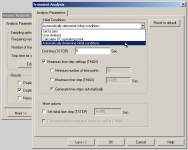
There are 4 different selectable
analysis choices.
See my attached MultiSim capture!
The default works okay when Fourier and using ideal DC voltage supply.
And of course is no problem run THD analys.
Because this will approach a stable value after some time Run.
But Fourier is sort a 'momentary capture'
and so it wont work good, unless there is, like you say, 'stability' in circuit.
Attachments
lineup,
I hope that someone else, who has experience with EWB, will comment, because I have no experience with it. The most I can offer is probably to relate how I can do some of these things in LT-Spice (which is a free download from Mixed-signal and digital signal processing ICs | Analog Devices , and is very, very good).
In LT-Spice, after a "Transient" (i.e. time-domain) simulation run is completed (OR if I have interrupted it), the main remaining result is usually the set of plot displays that I have told it to generate, showing various voltages, currents, power dissipations, impedances, or whatever I selected, graphed versus time.
I can then tell LT-Spice to generate and display a plot of an FFT (Fast Fourier Transform) of any or all of the displayed waveforms.
Also, if I want to first "zoom in" the display, so that the display-window shows the waveform(s) for only a smaller portion of the original run-time, then I can use the mouse and drag a rectangle around the portion that I want to see magnified. If I THEN select "FFT" (i.e. after magnifying, like that, in order to see only a smaller portion of the original waveform display), then the FFT dialog also offers a choice between calculating the FFT over the entire run-time, or only over the currently-zoomed window's displayed portion of the run-time. It also always allows setting #points used, etc etc.
There is also a separate and completely different Fourier "command", which can be used to automatically calculate THD. It must be entered onto the LT-Spice schematic, before a run is started, and has a format like .four freq #harmonics #cycles signal_name , where the #cycles parameter is the number of signal cycles that will be used, which are always taken from the END of the run-time, from the signal "signal_name". For that one, too, I have to be careful that the signal has reached a completely-stable "steady-state" condition, if I want the most-accurate results.
- Tom Gootee
Make Easy and Cheap PCBs at Home, Curve Tracer (& DIY Kits), Building Inexpensive CNC Machines at Home, Good Used Electronic Test Equipment for sale; Tektronix, HP, and many others: Oscilloscope, Signal generator, Power Supply, Spectrum Analyzer, Fre
-
MEASURING AND SPICE-MODELING A POWER TRANSFORMER
teemuk,
After further LT-Spice testing, the two-coupled-inductors transformer model, that I mentioned earlier in this thread (which was derived from your model), seemed to not work correctly, for modeling the 56VA transformer for the power supply that I had already designed and built. That was possibly because I didn't have good parameters for the model. I tried tweaking the parameters, quite a bit, and using my transformer's measured winding resistances, testing just the transformer model with an ideal voltage source input and various resistances across the output. But even the models that seemed to perform OK, that way, still suffered from not having enough available power at the output, when used in my existing PSU's LT-Spice simulation.
So, I went looking for a better way to measure transformers, and model them in Spice, and found this:
http://www.onsemi.com/pub/Collateral/AN1679-D.PDF ,
which I found referenced in this thread:
http://groups.google.com/group/sci....read/thread/90a5f710a1dda388/f02846e2cededb30
Look at Page 4 of the appnote AN1679-D.PDF, Steps 1 through 8, and Figure 8.
Like you, I don't have an inductance meter or bridge, either. So, I calculated approximate inductance using an oscilloscope's display of the voltage resulting from applying a square wave, using L= V/(di/dt) and the measured resistance. I used the scope's built-in 1 kHz calibration output, for the square wave.
Below, I'll go through the steps from Page 4 of the appnote referenced above, and show how I measured the transformer and derived my model parameters.
--------------------------------------------
Transformer modeled in this example: Triad Magnetics VPP36-1560 (same as Hammond 183K36), 56VA, dual 115V primaries, dual secondaries (36VCT @ 1.56A or 18V @ 3.12A), PCB mounted.
I use this transformer with the secondaries in parallel. And for 115V-117V inputs, the primaries are also used in parallel, in my application. So I modeled one primary and one secondary as "the transformer model" and then, in my LT-Spice PSU circuit model, used two of those transformer models in parallel, with 115V-117V input. But any other primary/secondary configurations can be used just as easily, once a transformer model representing one primary and one secondary has been created.
The following is a description of how I implemented the eight steps from Page 4 of the appnote referenced above (AN1679-D.PDF from onsemi.com):
1. Calculate N= Np/Ns = Vp/Vs. I didn't measure, using the Vp and Vs specs instead:
N=116v/18v = 6.444
2. Measure primary inductance, with secondary OPEN-circuit:
a) Attached scope probe tip to calibration output. Adjusted probe's compensation trimmer until square wave looked square. (This is important.)
b) Attached scope probe tip and scope calibration squarewave output to one of tranformer's primary pins and attached probe's ground clip to other (corresponding) primary pin. Scope display showed pulses with tops sloping downward (from left to right), with peaks at 0.3V, sloping from 0.3v to 0.25v over 0.3 ms.
Noted that V = L(di/dt) --> L = V/(di/dt).
Resistance of primary was already measured as 20.85 Ohms, so
di/dt approx= [(0.3v-0.25v)/20.85 Ohms]/0.3ms = 7.9936 A/S
Used V=0.3v (peak value; could also use 0.25v; maybe should use average of 0.3 and 0.25):
V = L(di/dt) --> L = V/(di/dt) = 0.3/7.9936 = .03753 = 37.53 mH
Lpsopen = 37.53 mH
3. Measure primary inductance, with secondary SHORT-circuited:
Performed same procedure as in step 2, above, except had a wire jumper connected between (corresponding) secondary's pins.
Lpsshort = 2.5 mH
4. Compute coupling coefficient k = sqrt(1-Lpsshort/Lpsopen):
k = sqrt(1-(.0025/.03753)) = 0.966
5. Compute L11 = (1 - k)(Lpsopen) = (1 - 0.966)(.03753) = .001276
L11 = 1.276 mH
6. Compute L12 = (1 - k)(Lpsopen)/(N^2)
= (1 - 0.966)(.03753)/(6.444^2) = .00003073
L12 = 0.03073 mH
7. Compute Lm = (k)(Lpsopen) = (0.966)(.03753) = .03625
Lm = 36.35 mH
8. Rprimary and Rsecondary resistances are measured with ohm meter:
Measured resistances across primary and secondary and then subtracted, from each one, the resistance measured with the Ohm meter's probes shorted together:
Rp = 20.85 Ohms
Rs = 0.73 Ohms
Now, see the schematic in Figure 8 of the appnote (AN1679-D.PDF from onsemi.com, linked-to above).
Note that the transformer in Figure 8 is an IDEAL transformer.
For the Spice model of the ideal transformer, I labeled the ideal transformer's input nodes as "ID1+" and "ID1-", and had no downstream connections to them. For the ideal transformer's output, I used a "bv" (behavioral voltage) source, and set the voltage to V=0.15517*( V(ID1+) - V(ID1-) ), where the 0.15517 = 1/N, using the N calculated in Step 1, above. i.e. 116VAC RMS input gives 18VAC RMS output.
Created schematic as shown in Figure 8 of appnote, with ideal voltage source input (Used 164V @ 60 Hz, since 116VAC RMS input X 1.414 = 164V 0-peak input): Connected Rp, Lm, and L11 in series (from ideal voltage source's + to - terminals, in the sequence just given), across input source. Node for input source's "+" terminal and top of Rp was labeled "ID1+". Node between Lm and L11 was labeled "ID1-". Inserted bv (behavioral voltage) source to the right of nodes ID1+ and ID1- (but NOT connected to them). Set V=0.15517*( V(ID1+) - V(ID1-) ), for bv source (by right-clicking on bv source, clicking on "Value" field, and entering the V expression just given). Inserted Rs and L12 in series, from bv source's "+" terminal to overall output terminal 1 of 2. Connected bv source's "-" terminal to overall output terminal 2 of 2. Inserted a 1000Meg resistor from ideal input voltage source's "-" terminal to Ground, so Spice wouldn't complain about "floating nodes".
It works!
Unfortunately, using the behavioral voltage source for the ideal transformer model, the way I did, means that the conditions at the secondary winding cannot affect the primary winding in any way. There should be a way to model the ideal transformer so that the coupling would work in both directions. But I couldn't immediately think of one. If anyone knows, or can imagine, a better way to try doing it, please let us know.
- Tom Gootee
http://www.fullnet.com/~tomg/index.html
-
teemuk said:Ain't that many transformer manufacturers publishing decent specs. Most manufacturers list only VA rating and maybe mounting configuration, diameter and weight. Why not primary/secondary inductances, winding resistances and parallel capacitances. It's a damn shame.
I have used following to simulate 250VA 230-48 transformer:
Lp = 10H, series resistance 6,4 ohms
Ls = 0,45H, series resistance 1,5 ohms.
The resistances are real measured values. The primary inductance was guessed based on some article I read yours ago (I do not have an inductance meter) and the secondary inductance is selected to give the specified voltage to moderate load.
My point is to say that if you know some specs of the actual part you can at least make a decent model which, in simple applications, works pretty well. I have noted that the model tends to sag pretty early, though. Something like this is also a highly simplifed version of an actual transformer and one has to take that in account when running simulations. For example, I wouldn't dare to trust into its accuracy in SMPS sims.
Edit: Inspired by this thread I did a quick search on primary inductances... again with mediocre luck. Fortunately, Rod Elliott's site (http://sound.westhost.com/xfmr2.htm) lists some measurements, which seems to indicate I estimated the inductance to be too low when I came up with the described model. 40 - 50H could be a more realistic value for a 250VA toroid.
teemuk,
After further LT-Spice testing, the two-coupled-inductors transformer model, that I mentioned earlier in this thread (which was derived from your model), seemed to not work correctly, for modeling the 56VA transformer for the power supply that I had already designed and built. That was possibly because I didn't have good parameters for the model. I tried tweaking the parameters, quite a bit, and using my transformer's measured winding resistances, testing just the transformer model with an ideal voltage source input and various resistances across the output. But even the models that seemed to perform OK, that way, still suffered from not having enough available power at the output, when used in my existing PSU's LT-Spice simulation.
So, I went looking for a better way to measure transformers, and model them in Spice, and found this:
http://www.onsemi.com/pub/Collateral/AN1679-D.PDF ,
which I found referenced in this thread:
http://groups.google.com/group/sci....read/thread/90a5f710a1dda388/f02846e2cededb30
Look at Page 4 of the appnote AN1679-D.PDF, Steps 1 through 8, and Figure 8.
Like you, I don't have an inductance meter or bridge, either. So, I calculated approximate inductance using an oscilloscope's display of the voltage resulting from applying a square wave, using L= V/(di/dt) and the measured resistance. I used the scope's built-in 1 kHz calibration output, for the square wave.
Below, I'll go through the steps from Page 4 of the appnote referenced above, and show how I measured the transformer and derived my model parameters.
--------------------------------------------
Transformer modeled in this example: Triad Magnetics VPP36-1560 (same as Hammond 183K36), 56VA, dual 115V primaries, dual secondaries (36VCT @ 1.56A or 18V @ 3.12A), PCB mounted.
I use this transformer with the secondaries in parallel. And for 115V-117V inputs, the primaries are also used in parallel, in my application. So I modeled one primary and one secondary as "the transformer model" and then, in my LT-Spice PSU circuit model, used two of those transformer models in parallel, with 115V-117V input. But any other primary/secondary configurations can be used just as easily, once a transformer model representing one primary and one secondary has been created.
The following is a description of how I implemented the eight steps from Page 4 of the appnote referenced above (AN1679-D.PDF from onsemi.com):
1. Calculate N= Np/Ns = Vp/Vs. I didn't measure, using the Vp and Vs specs instead:
N=116v/18v = 6.444
2. Measure primary inductance, with secondary OPEN-circuit:
a) Attached scope probe tip to calibration output. Adjusted probe's compensation trimmer until square wave looked square. (This is important.)
b) Attached scope probe tip and scope calibration squarewave output to one of tranformer's primary pins and attached probe's ground clip to other (corresponding) primary pin. Scope display showed pulses with tops sloping downward (from left to right), with peaks at 0.3V, sloping from 0.3v to 0.25v over 0.3 ms.
Noted that V = L(di/dt) --> L = V/(di/dt).
Resistance of primary was already measured as 20.85 Ohms, so
di/dt approx= [(0.3v-0.25v)/20.85 Ohms]/0.3ms = 7.9936 A/S
Used V=0.3v (peak value; could also use 0.25v; maybe should use average of 0.3 and 0.25):
V = L(di/dt) --> L = V/(di/dt) = 0.3/7.9936 = .03753 = 37.53 mH
Lpsopen = 37.53 mH
3. Measure primary inductance, with secondary SHORT-circuited:
Performed same procedure as in step 2, above, except had a wire jumper connected between (corresponding) secondary's pins.
Lpsshort = 2.5 mH
4. Compute coupling coefficient k = sqrt(1-Lpsshort/Lpsopen):
k = sqrt(1-(.0025/.03753)) = 0.966
5. Compute L11 = (1 - k)(Lpsopen) = (1 - 0.966)(.03753) = .001276
L11 = 1.276 mH
6. Compute L12 = (1 - k)(Lpsopen)/(N^2)
= (1 - 0.966)(.03753)/(6.444^2) = .00003073
L12 = 0.03073 mH
7. Compute Lm = (k)(Lpsopen) = (0.966)(.03753) = .03625
Lm = 36.35 mH
8. Rprimary and Rsecondary resistances are measured with ohm meter:
Measured resistances across primary and secondary and then subtracted, from each one, the resistance measured with the Ohm meter's probes shorted together:
Rp = 20.85 Ohms
Rs = 0.73 Ohms
Now, see the schematic in Figure 8 of the appnote (AN1679-D.PDF from onsemi.com, linked-to above).
Note that the transformer in Figure 8 is an IDEAL transformer.
For the Spice model of the ideal transformer, I labeled the ideal transformer's input nodes as "ID1+" and "ID1-", and had no downstream connections to them. For the ideal transformer's output, I used a "bv" (behavioral voltage) source, and set the voltage to V=0.15517*( V(ID1+) - V(ID1-) ), where the 0.15517 = 1/N, using the N calculated in Step 1, above. i.e. 116VAC RMS input gives 18VAC RMS output.
Created schematic as shown in Figure 8 of appnote, with ideal voltage source input (Used 164V @ 60 Hz, since 116VAC RMS input X 1.414 = 164V 0-peak input): Connected Rp, Lm, and L11 in series (from ideal voltage source's + to - terminals, in the sequence just given), across input source. Node for input source's "+" terminal and top of Rp was labeled "ID1+". Node between Lm and L11 was labeled "ID1-". Inserted bv (behavioral voltage) source to the right of nodes ID1+ and ID1- (but NOT connected to them). Set V=0.15517*( V(ID1+) - V(ID1-) ), for bv source (by right-clicking on bv source, clicking on "Value" field, and entering the V expression just given). Inserted Rs and L12 in series, from bv source's "+" terminal to overall output terminal 1 of 2. Connected bv source's "-" terminal to overall output terminal 2 of 2. Inserted a 1000Meg resistor from ideal input voltage source's "-" terminal to Ground, so Spice wouldn't complain about "floating nodes".
It works!
Unfortunately, using the behavioral voltage source for the ideal transformer model, the way I did, means that the conditions at the secondary winding cannot affect the primary winding in any way. There should be a way to model the ideal transformer so that the coupling would work in both directions. But I couldn't immediately think of one. If anyone knows, or can imagine, a better way to try doing it, please let us know.
- Tom Gootee
http://www.fullnet.com/~tomg/index.html
-
Hello Tom,
your measurement of the primary inductance is by far too low!
The u of the lamination is very nonlinear and rise a lot with higher magnetization.
So you must do your measaurement of Lp with 60Hz and about 110V.
For modelling I think it´s better to use the coupled inductors but with k=1 and further parts,
because your try can transfer DC currents.
If I like to simulate this I use the arrangement you can see in the attachment (1 : 1 "DC" transformer).
Regards
Heinz!
Attachments
Heinz!,
Thanks for responding. And it's good to hear from you, again!
I am merely a beginning dabbler, in this. So I greatly-appreciate your information. I had suspected (and also read, on Usenet, just this morning) that I might need to use something closer to the operating conditions, to get good inductance (et al) measurements. Now, how can I get a measurement, without a special inductance meter? Or could it be sufficient to estimate? I'd like to be able to model the startup behavior, if possible.
Thanks again!
- Tom Gootee
Make Easy and Cheap PCBs at Home, Curve Tracer (& DIY Kits), Building Inexpensive CNC Machines at Home, Good Used Electronic Test Equipment for sale; Tektronix, HP, and many others: Oscilloscope, Signal generator, Power Supply, Spectrum Analyzer, Fre
Re: MEASURING AND SPICE-MODELING A POWER TRANSFORMER
Thanks for that link, Tom. That's a really good article. He explains that stuff really well.
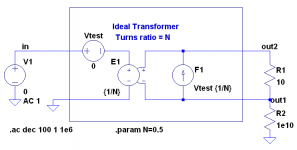
Well, I see Heinz has already posted something on this, but let me add a little bit also. I looked up the two-port parameters of an ideal transformer. The z and y matrices are undefined, but the h matrix is well defined. The parameters are:
h11=0
h12=1/N
h21=-1/N
h22=0
where N is the turns ratio.
Putting these into the two-port model with controlled sources gives the circuit pictured below.
gootee said:So, I went looking for a better way to measure transformers, and model them in Spice, and found this:
http://www.onsemi.com/pub/Collateral/AN1679-D.PDF
Thanks for that link, Tom. That's a really good article. He explains that stuff really well.
Unfortunately, using the behavioral voltage source for the ideal transformer model, the way I did, means that the conditions at the secondary winding cannot affect the primary winding in any way. There should be a way to model the ideal transformer so that the coupling would work in both directions. But I couldn't immediately think of one. If anyone knows, or can imagine, a better way to try doing it, please let us know.
Well, I see Heinz has already posted something on this, but let me add a little bit also. I looked up the two-port parameters of an ideal transformer. The z and y matrices are undefined, but the h matrix is well defined. The parameters are:
h11=0
h12=1/N
h21=-1/N
h22=0
where N is the turns ratio.
Putting these into the two-port model with controlled sources gives the circuit pictured below.
Attachments
Tom :
"Now, how can I get a measurement, without a special inductance meter?"
Tom,
take the primary voltage from a isolating variac and measure the primary current through the primary coil with a scope and a small shunt.
Rise the 60Hz voltage as long as the current looks like a sinus, or you reach the 110V.
From voltage and current you can calculate ZL.
Then subtract Rprim geometrically from ZL to get XL.
Together with the frequency (60Hz) you now can calculate Lp.
Andy,
thank´s for "dc-trafo", but please look to the left side :
2 voltage sources are switched parallel , E1 against V1 .
My stems from my old ewb5.1 simulator.
Heinz!
Attachments

powerbecker said:Andy,
thank´s for "dc-trafo", but please look to the left side :
2 voltage sources are switched parallel , E1 against V1 .
Wow, that really threw me off 🙂! And yet if you do an AC sim, calculating V(in)/I(Vtest), you'll see that the impedance looking into the primary is 40 Ohms over all frequency. That's exactly as you'd expect for the turns ratio and load on the secondary. But how can the impedance into a voltage source not be zero? If you follow the chain of dependencies for E1, its voltage depends on the secondary voltage, which in turn depends on the current through Vtest (first term in F1). So the voltage of E1 depends indirectly on the current through it. Its impedance might be zero, but only if the secondary is shorted. So E1 is really looking like a 40 Ohm resistor here. Of course, the impedance looking back into the secondary is zero because of the zero Ohm primary impedance.
My stems from my old ewb5.1 simulator.
I'd expect there would be several equivalent controlled-source models of the ideal transformer. My tattered old network theory book shows an F, G and H matrix for the ideal transformer. So I'd expect there'd be at least three different but equivalent models. I just did the one for the H matrix because I couldn't remember what the F and G matrices were.
I think you'll find that this model transforms the voltages, currents and impedances correctly.
- Status
- Not open for further replies.
- Home
- Amplifiers
- Power Supplies
- Anyone have SPICE models for PSU Toroidal Xfmr ??