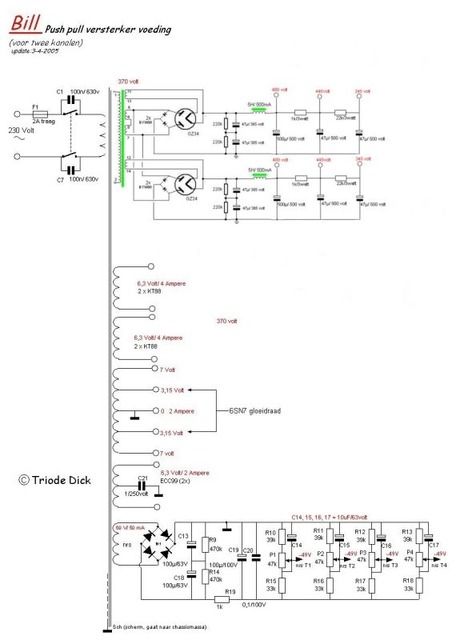
Just finished my latest amp project, PP KT88 integrated. It´s Triode Dicks BILL
with a converted PS that uses 2 GZ34 rectifiers
 .
.
Powered it up for the first time and I have hum. Strangely enough the hum dosn´t come instantly, it rather builds up to come to peak after about 30-40 sec´s. I have tried pulling the rectifiers out with the result of NO hum. So I tried pulling the KT88´s out and NO hum. I also tried playing some music with the hum humming away and the music was slurred and lacked power. I should have known better but I also tried pulling the 6SN7 out and this resulted in sparks of one of the ECC99´s, I believe I fried it so I have to order new ones now, sucks! 😡
there are pictures of the amp in the "pictures section"
Anyway, if anyone would be so kind to help me with this I would be very grateful.
Cheers
with a converted PS that uses 2 GZ34 rectifiers
Powered it up for the first time and I have hum. Strangely enough the hum dosn´t come instantly, it rather builds up to come to peak after about 30-40 sec´s. I have tried pulling the rectifiers out with the result of NO hum. So I tried pulling the KT88´s out and NO hum. I also tried playing some music with the hum humming away and the music was slurred and lacked power. I should have known better but I also tried pulling the 6SN7 out and this resulted in sparks of one of the ECC99´s, I believe I fried it so I have to order new ones now, sucks! 😡
there are pictures of the amp in the "pictures section"
Anyway, if anyone would be so kind to help me with this I would be very grateful.
Cheers
How is the heater supply wired up? To gnd or a positive bias? The LTP resistor (10kohms) could be two 5kohms in series, giving a perfect 65volt bias for the heaters.
Pulling the 6SN7 effectively gives b+ on the ECC99s grids, so they may have been blown by that. Bad luck on that part, but such things happen😉
Pulling the 6SN7 effectively gives b+ on the ECC99s grids, so they may have been blown by that. Bad luck on that part, but such things happen😉
What is your grounding scheme? Having two HT supplies sharing a secondary winding creates opportunities for problems, although it can be OK if done properly. The two pairs of silicon diodes will be in parallel, so it is likely that only one of each will conduct. This could inject hum into the ground unless the two HT supples share a ground connection. What would happen if one of these sets of diodes was snipped out (as may actually happen if they don't conduct).
How is the heater supply wired up? To gnd or a positive bias? The LTP resistor (10kohms) could be two 5kohms in series, giving a perfect 65volt bias for the heaters.
Pulling the 6SN7 effectively gives b+ on the ECC99s grids, so they may have been blown by that. Bad luck on that part, but such things happen😉
Hello SemperFi
Not quite sure I follow you here. The heater supply is wired exactly as in the schematic. The KT88´s are biased by the bias supply -58V to cathode.... Please explain what the LTP resistors you are refering to are.
Cheers
Last edited:
What is your grounding scheme? Having two HT supplies sharing a secondary winding creates opportunities for problems, although it can be OK if done properly. The two pairs of silicon diodes will be in parallel, so it is likely that only one of each will conduct. This could inject hum into the ground unless the two HT supples share a ground connection. What would happen if one of these sets of diodes was snipped out (as may actually happen if they don't conduct).
Hello DF96
The grounding is wired exactly as in the schematic. Both HT supplies have separate ground bus that goes to star ground.
What would be the option of having pairs of diodes? If you are right what would you suggest instead?
Here are better pictures of schematics:
PSU
AMP
Cheers
I dont think the problem is in the schematic; lots of "bills" have been build without hum.
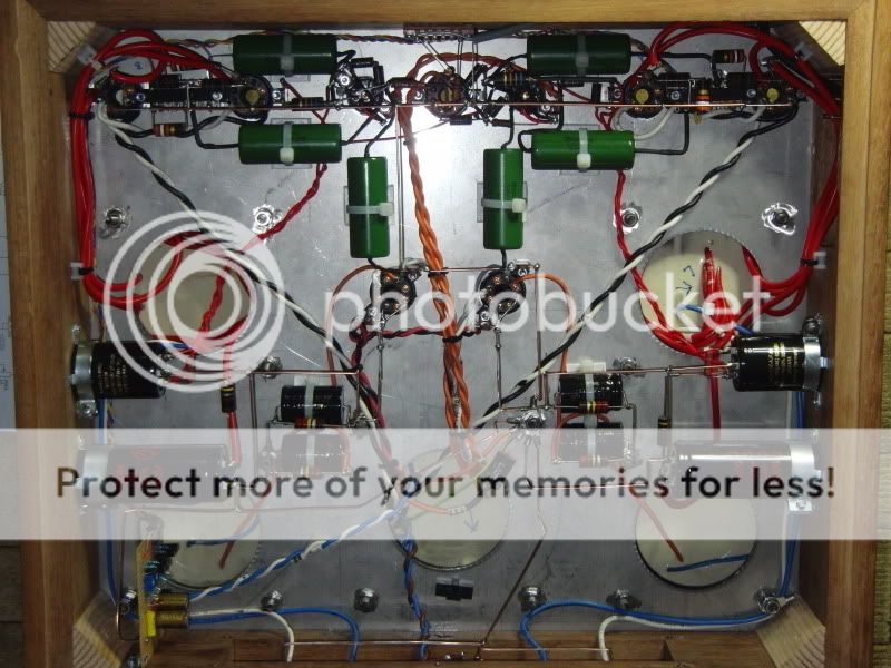
Could you make a picture of the inside of your amp?
You should probably never pull a tube from a working amp; you could fry al kinds of things, (including your fingers)
By adjusting the bias does the hum change?
Do you have a scope or multimeter?
Try measuring your b+, but in the AC setting of the multimeter, and give us the value.
Succes, Paul
I dont think the problem is in the schematic; lots of "bills" have been build without hum.
Could you make a picture of the inside of your amp?
You should probably never pull a tube from a working amp; you could fry al kinds of things, (including your fingers)
By adjusting the bias does the hum change?
Do you have a scope or multimeter?
Try measuring your b+, but in the AC setting of the multimeter, and give us the value.
Succes, Paul
Hello Pauldune
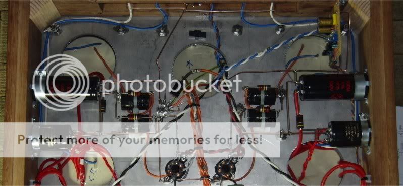
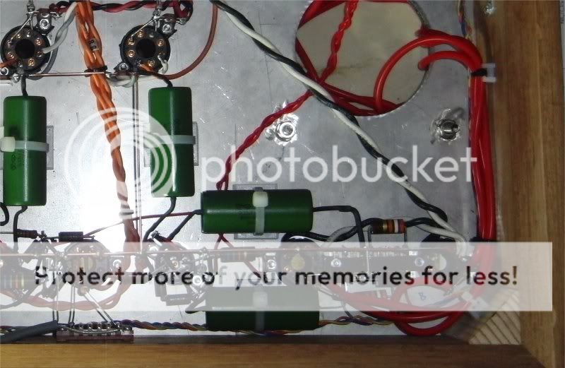
Here is a pictura of the internal wireing
An externally hosted image should be here but it was not working when we last tested it.
An externally hosted image should be here but it was not working when we last tested it.
I can ensure you I never pull tubes from a powered up amp, I turned it of before I pulled the tubes and then powered it up.
I did try adjusting the bias but the hum didn´t change.
I do have a multimeter
I have measured all the voltagepoints and they are within 5% of the voltages in the schematic. I havn´t measured B+ vith AC setting on the multimeter. What would I be looking for?
Im not able to do any thing at the moment due to beeing out of ECC99 tubes that where frried, stupid of me.
Anyway, if you have any ideas of what I could check when I get my new ECC99 tubes please let me know and I will try them.
Kind regards......
Last edited:
It's just a convenient place to bias up your heaters............
If you replace the 10K R with 2 5K's in series, and attach your heater winding center tap between them, it will bias up the heaters to around 65V, which can help reduce hum by reverse biasing the cathode-heater filament in the tube. Sometimes hum can be caused by the current leakage of the pseudo-diode formed between the filament and the cathode.
If you have significant hum, I would check other stuff, like how the volume pot is grounded, how the tube sockets are wired for the heaters, etc.
Hello SemperFi
Not quite sure I follow you here. The heater supply is wired exactly as in the schematic. The KT88´s are biased by the bias supply -58V to cathode.... Please explain what the LTP resistors you are refering to are.
Cheers
If you replace the 10K R with 2 5K's in series, and attach your heater winding center tap between them, it will bias up the heaters to around 65V, which can help reduce hum by reverse biasing the cathode-heater filament in the tube. Sometimes hum can be caused by the current leakage of the pseudo-diode formed between the filament and the cathode.
If you have significant hum, I would check other stuff, like how the volume pot is grounded, how the tube sockets are wired for the heaters, etc.
Hi Boywonder
Ok, you mean the CT winding for the ECC99 on the TX connected to CT in this schematic?
An externally hosted image should be here but it was not working when we last tested it.
I do have significant hum, the volume pot looks ok but what do you mean when you say "how the tube sockets are wired for the heaters"?
Thanks for suggestions
Cheers
Last edited:
Take a 330K and a 68K 1/2W resistors.
Join 'em together.
Place the end of the 68K to ground and the end of the 330K to the B+++ line.
Disconnect the Centre-Tap off the 6SN7 Heater supply At The Mains Transformer--Currently its attached to Ground.
Attach the centre-point of the resistors to the point on the Mains-Trans. that you disconnected the Ground from....
Job done.....🙂
Take a 330K and a 68K 1/2W resistors.
Join 'em together.
Place the end of the 68K to ground and the end of the 330K to the B+++ line.
Disconnect the Centre-Tap off the 6SN7 Heater supply At The Mains Transformer--Currently its attached to Ground.
Attach the centre-point of the resistors to the point on the Mains-Trans. that you disconnected the Ground from....
Job done.....🙂
Helo Alistar E
Which B+ line? you mean the one feeding 6SN7 @ 345V??
Cheers
Doesn't matter which. Point is to get a positive voltage for the heater circuit. Any voltage divider will do.
To be honest this heater biasing is most noticable on high gain circuits. Not convinced this is your problem. But it may help a little. If yoy heaters are grounded you shouldnt have such a hum problem. Are the heaters for the output tubes grounded?
To be honest this heater biasing is most noticable on high gain circuits. Not convinced this is your problem. But it may help a little. If yoy heaters are grounded you shouldnt have such a hum problem. Are the heaters for the output tubes grounded?
Hello SemperFi
No, the output tubes are biased by the bias supply. The bias supply is grounded from possitive side to ground. The output tubes heaters are not not grounded. Wouldent the hum be present when i pulled the rectifiers if it where the power tubes that was the problem? What would you say about hum pot´s?
Cheers
How are the silicon diodes grounded? This is not clear in the pictures. You seem to have two separate HT supplies on opposite sides of the chassis, with a common star point in the middle yet sharing the secondary and also, in effect, sharing the diodes. This means that how the diodes are grounded is important. You may have created a big loop for the charging pulses. Also, do you maintain strictly separate grounds for each channel or bring them together somewhere apart from the star point?
I must confess I am always suspicious of apparently tidy layouts!
I must confess I am always suspicious of apparently tidy layouts!
How are the silicon diodes grounded? This is not clear in the pictures. You seem to have two separate HT supplies on opposite sides of the chassis, with a common star point in the middle yet sharing the secondary and also, in effect, sharing the diodes. This means that how the diodes are grounded is important. You may have created a big loop for the charging pulses. Also, do you maintain strictly separate grounds for each channel or bring them together somewhere apart from the star point?
I must confess I am always suspicious of apparently tidy layouts!
Hi DF96
The diodes are grounded to the negative side of the first 50uf capacitors that are parallelled with resistors. Yes, I have 2 separate HT sup on each side sharing the same sec from TX. I dont know about the loop but the only thing that differs in the actuall wiering and schematic is the sequense they are grounded, look at the picture and schematic. I have one ground bus for the 1st, 2nd and third stage, all tubes share the same ground. PSU has separate ground.
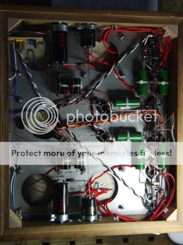
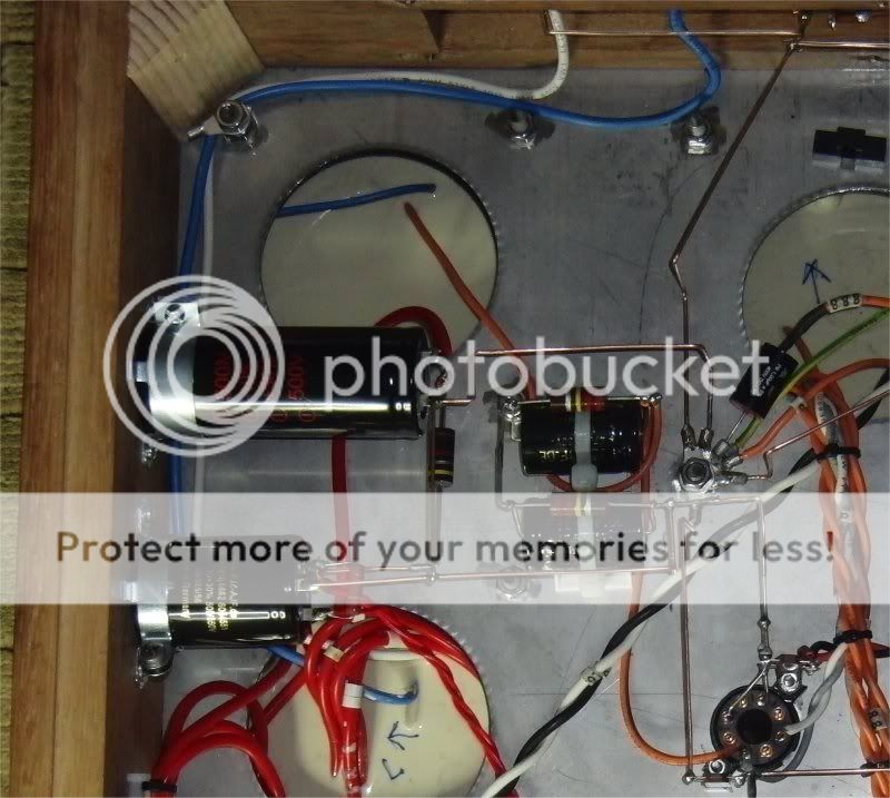
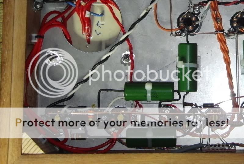
Heres a pic of the PS

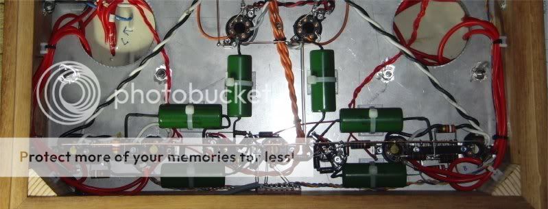
Here are some pic´s of the front
Hey! you should se me eat, I do this at a point of perfection my girlfriend says! 🙂
Cheers
Last edited:
Im talking about heater bias, not biasing the tubes. Heater bias is wrong term I guess, but is commonly used to describe a voltage other than gnd to connect the heater wiring.
I can't see the diodes in the picture. Anyway, if the diodes for each channel are connected directly to the reservoir capacitor -ve for each channel (the correct wiring for separate secondaries) then this could be the source of the hum. Remember that the common secondary and the common star point mean that the two diodes conducting (one per channel) are connected in parallel. They won't be perfectly matched so one diode will take most of the current. This means that the ground connection between the two reservoir caps will carry ripple current. On the opposite cycle it may go the same way or the other way, depending on the diode matching/mismatching. These two ground connections are thus dirty and must not be used for anything else. You seem to use them to connect to the -ve on the smoother cap for each channel. Thus you are injecting ripple into the smoother cap ground. Bad hum is inevitable.
You need to rethink your grounding. Think about where the currents go. Regard each piece of ground wire as having a significant resistance across which a current will generate a voltage. Also, the +ve lead to the reservoir caps should follow the -ve lead so it minimises the loop area enclosed by charging pulses.
You need to rethink your grounding. Think about where the currents go. Regard each piece of ground wire as having a significant resistance across which a current will generate a voltage. Also, the +ve lead to the reservoir caps should follow the -ve lead so it minimises the loop area enclosed by charging pulses.
If u pull the rectifiers, how are the tubes supposed to hum? Offcourse the amp goes dead without a b+.
.....
I did try adjusting the bias but the hum didn´t change.
I do have a multimeter
I have measured all the voltagepoints and they are within 5% of the voltages in the schematic. I havn´t measured B+ vith AC setting on the multimeter. What would I be looking for?
Anyway, if you have any ideas of what I could check when I get my new ECC99 tubes please let me know and I will try them.
Kind regards......
Well if you measure b+ with ac setting, you measure the ripple! With a pushpull some ripple is allowed, because if both end tubes are equally biased this canceles out.
But since you already said that hum didnt change with bias setting, maybe its already ruled out.
But doesnt hurt to check anyway.
If i look at your pictures, i think i see something....
All supplycap groundpoles (-) are connected to the starground, right?
I wouldn do that...
If you connect all gounds of rectifier and caps together, directly without going to the starground.
And then make the connection to the starground ONLY on the last cap.
That way you isolate the current spikes from recharging the caps.
It is possible that you have also a large groundloop because of the 2 rectifiersets on a single xformer secundary.
Easy to test:disconnect 1 of the supply chains temporary, so 1 channel is shut down. Then listen is the hum is gone on the working channel.
Paul
- Status
- Not open for further replies.
- Home
- Amplifiers
- Tubes / Valves
- Anyone care for some troubleshooting? Hum issue