ok, MORE pictures... been really getting some use out of the new digital camera. thankfully i have a 512mb memory stick 🙂
here are the full pics for the amp and preamp, top and bottom. i kept them a bit bigger so you can see more detail, so they are around 150k each, so i wouldnt recommend using dialup for them.
btw, i have ALL of these pics still in their 5.0MP original resolution if you want even more detail, but they are 2.0Mb each.
also, on the amp board, i noticed a few chips and looked them up...
there is a pair of IR2101, which are "high-voltage, high-speed power MOSFET and IGBT drivers". (datasheet here: http://www.irf.com/product-info/datasheets/data/ir2101.pdf), and a single IR2113 (i guess they go together?).
also, from looking through the traces coming out of the ribbon cable, it seems like a few go to the cluster of small chips in between the second and third cap that i removed. from there, they go straight to the IR2101 chips, then to the FETS. there are 3 IC's here, can i can only read one of them without a magnifying glass. the one i can read is a motorola HC11, which is a microcontroller... the other appears to be a TI HC14, which is a "high speed CMOS logic hex inverting schmitt trigger", whatever that means. the third one appears to be a phillips 74hc27d (my eyes REALLY hurt now from straining to see it). i couldnt find anything exact, but it also appears to be a CMOS chip.
so, that is what i found, here are the pictures... it seems stocker might be right, maybe this doesnt use just a simple line-level signal, maybe it uses something else that is fed to the amp. that could suck.
http://www.cowanrg.mesanetworks.net/projects/images/velodyne/preamp_top_full.jpg
http://www.cowanrg.mesanetworks.net/projects/images/velodyne/preamp_bottom_full.jpg
http://www.cowanrg.mesanetworks.net/projects/images/velodyne/amp_top_full.jpg
http://www.cowanrg.mesanetworks.net/projects/images/velodyne/amp_bottom_full.jpg
That would only suck if you were unwilling to take the time...
I'm not. Were I in your shoes, I would have a house full of way-too-powerful amplified speakers, having figured these out through and through, if at all possible!
Looking at photos. Hang on. Can you post the high resolution versions to a website so we can look JIC?
/edit: this .jpg compression is killing me. change the above "can you" to will you please!
/edit 2: I guess I should have said I meant ALL the big caps & glue on the amp. board.
/edit 3: I guess it wouldn't hurt to pull the ribbon cable off the amp. PCB to see what's underneath. I know it's a real hassle to pull a jumper block so for now let's see where we can get using eyeballs and multimeters for the preamp side of the cable
I'm not. Were I in your shoes, I would have a house full of way-too-powerful amplified speakers, having figured these out through and through, if at all possible!
Looking at photos. Hang on. Can you post the high resolution versions to a website so we can look JIC?
/edit: this .jpg compression is killing me.
change the above "can you" to will you please!/edit 2: I guess I should have said I meant ALL the big caps & glue on the amp. board.
/edit 3: I guess it wouldn't hurt to pull the ribbon cable off the amp. PCB to see what's underneath. I know it's a real hassle to pull a jumper block so for now let's see where we can get using eyeballs and multimeters for the preamp side of the cable
I am getting a sneaking suspicion that this will fill your memory stick to overflowing. The problem with direct-overhead shots on a board with tall components is that something else is sure to get blocked. This is also looking to be quite a lot of  for you!
do the invisible model numbers show up when you look at the uncompressed images? If not, here is a trick for you: when a model number on a semiconductor device is illegible but there is some relief to the letters, positive or negative, you can make them stand out like a sore thumb (sometimes) by either shifting the PCB relative to the light source and your eye OR rubbing a *little* heat sink compound on the component and wiping it off. It fills the texture and can make the lettering legible.
for you!do the invisible model numbers show up when you look at the uncompressed images? If not, here is a trick for you: when a model number on a semiconductor device is illegible but there is some relief to the letters, positive or negative, you can make them stand out like a sore thumb (sometimes) by either shifting the PCB relative to the light source and your eye OR rubbing a *little* heat sink compound on the component and wiping it off. It fills the texture and can make the lettering legible.
well, dont worry about my poor memory stick, i have a 512mb and a pair of 128's. they wont be filled anytime soon.
the model numbers of the chips cant show up on any photos, they are just too small, and it appears like the glue took off the paint on them, so you can only see the engraving. that is why it was so hard to see.
i can read you any chips that you need though. as far as high res pics, let me know WHICH ones you want. all of them is almost 200mb, which is far too much for my website.
i will pull off all the big caps and the glue from the amp board.
do those IC's mean anythig to you? does the fact that having CMOS chips on the amp board mean that its not using a standard audio signal?
rabstg,
if you are around, any of this looking at all familiar to you?
CMOS can be used for almost anything, properly configured. I think the last two of the preamp at high resolution for starters. Plus when you get the caps and glue off the amp board, those as well. Try the tip with the white grease... it works well when you have only engraved lettering. Try it before taking the pictures, and it would be helpful!
Pull the big bridge rectifier too, now that I think of it, from the amp board, and see if you can get a good shot down between the output devices and that last toroid as well.
Pull the big bridge rectifier too, now that I think of it, from the amp board, and see if you can get a good shot down between the output devices and that last toroid as well.
i was thinking about pulling out the toroid on the amp board as well.
and it seems like i can only have about 4-6 high res pics on my site right now...
so, im thinking of just doing one of each of the TOP of the amp and preamp board... the back is easy enough to see in lower res right?
and it seems like i can only have about 4-6 high res pics on my site right now...
so, im thinking of just doing one of each of the TOP of the amp and preamp board... the back is easy enough to see in lower res right?
ok, two more pictures. these are about as good as i can get right now.
the problem isnt really the flash as much as the board. its VERY shiny. it reflects any light i try and put on it. its nighttime right now, so its all artificial light, so its hard to get great lighting on it.
but these seem ok. i cant seem to get a good pic of the fets because the focus isnt going in the right place. it will take some playing around with to figure out. ill post one when its daytime again.
any ideas though? if not, ill give it a rest for awhile then, because im getting tired of taking pictures 🙂
Stocker,
check your mail though.
http://www.cowanrg.mesanetworks.net/projects/images/velodyne/preamp_top_hires.jpg
http://www.cowanrg.mesanetworks.net/projects/images/velodyne/amp_top_hires.jpg
The bottoms of the PCBs should be ok with the lo-res for now. Pulling the big toroid wouldn't hurt, but be sure to remember (label) where the leads go! 
Yeah, my email is kinda slow. I think it's an operator error type of thing.
Let me look at these for a while.
One thing with the focus on your camera:
With most digital cameras, there is a mode that's for shooting the Wayne's World Extreme Close-Up that has a flower (tulip) icon. Use the display to check the focus...
Hold down the button halfway...something should happen to tell you it's focused...a light or something. Then move the camera so the part you want is framed and in focus. It should hold the focus. MOST cameras will have a function for holding the focus point where you want it, even if you have to dig through the manual.
Well look at it this way: here is some good practice for you with your camera!
couple of questions:
on the top of the preamp, by the pot side, there is a 2 pin connector labelled P1 and P2...for what?
What are the model numbers of the regulators on the preamp board?
May need a better-focused shot of the right side later. Maybe not, if you are willing to wait on the mail... 😉 But these photos will probably help a LOT, especially if I can get them to print right at about 4x life size.
to the right side of the pots, if its the red 2-pin connector, that is the audio input from the RCA jacks.
i think ill wait in the mail. im going through batteries like its going out of style.
i think ill wait in the mail. im going through batteries like its going out of style.
I was hoping that was it. Wouldn't want it to be something rediculous like a 12.37582MHz clock signal input from the internet or something! 😱
Well anyhow, it makes things a little easier to follow to know that.
Merry Christmas!
P.S.:
re
charge
a
ble
batteries. 😉 😀
/edit: getting punchy. Need to go to bed.
Well anyhow, it makes things a little easier to follow to know that.
Merry Christmas!
P.S.:
re
charge
a
ble
batteries. 😉 😀
/edit: getting punchy. Need to go to bed.
hah, you sound like you need sleep. same here. i need it, the xmas season is hell on us salesmen...
im going to set this project aside for a few weeks, to allow me to finish (yes, FINISH), my bosoz for my dad (its a late xmas present...). but if anyone has any ideas or input, feel free to post it! its amazing that there is almost NO information about these sub plates... very strange considering how popular velodyne subs are, and they really only use 2-3 different plate amps for their whole line.
im going to set this project aside for a few weeks, to allow me to finish (yes, FINISH), my bosoz for my dad (its a late xmas present...). but if anyone has any ideas or input, feel free to post it! its amazing that there is almost NO information about these sub plates... very strange considering how popular velodyne subs are, and they really only use 2-3 different plate amps for their whole line.
I had a set of Philips MFB loudspeakers in the 80s, Philips developed the first motional feedback loudspeakers in 1978.
At the time they did not sell that well because of the high price for small loudspeakers, a couple of years later Philips stopped production and sold the concept.
Here in Eindhoven they seem to have a tradition in selling their technology: CD-DVD-Plasma tv's
Today still, these MFB loudspeakers are wanted items, $ 400 for a 20 year old set is not unusual.
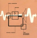
The IC in your Velodyne plate amp is the comparator of the motion feedback signal and the entrance signal, not surprising that it is a Philips programmable.
I added a block diagram pic for the Philips MFB below, it probably matches the Velodyne's.
The feedback circuit on one of the MFB's i had disfunctioned, without it the loudspeaker sounded no good.
At the time i had a relative working at the Philips development lab who fixed the feedback for me.
MFB makes it possible to use a class D amplifier on a woofer that normally would not be able to have sufficient control over the speaker.
Velodyne builds awesome speakers, my guess is that the one you've shown needs quite a hefty amplifier to make it sound promising without MFB.
At the time they did not sell that well because of the high price for small loudspeakers, a couple of years later Philips stopped production and sold the concept.
Here in Eindhoven they seem to have a tradition in selling their technology: CD-DVD-Plasma tv's
Today still, these MFB loudspeakers are wanted items, $ 400 for a 20 year old set is not unusual.
The IC in your Velodyne plate amp is the comparator of the motion feedback signal and the entrance signal, not surprising that it is a Philips programmable.
I added a block diagram pic for the Philips MFB below, it probably matches the Velodyne's.
The feedback circuit on one of the MFB's i had disfunctioned, without it the loudspeaker sounded no good.
At the time i had a relative working at the Philips development lab who fixed the feedback for me.
MFB makes it possible to use a class D amplifier on a woofer that normally would not be able to have sufficient control over the speaker.
Velodyne builds awesome speakers, my guess is that the one you've shown needs quite a hefty amplifier to make it sound promising without MFB.
Attachments
So you say it *may* not be a good amp, without the feedback from the woofer? Hmmm... I still bwant to try it!
i think he's referring to the speaker, not the amp.
"Velodyne builds awesome speakers, my guess is that the one you've shown needs quite a hefty amplifier to make it sound promising without MFB."
so, he's not saying the amp or speaker is bad, just that the driver needs one helluva amp to drive it, thus the servo.
dont let that stop you stocker, keep working 😉
Yep, thats what i said.
I am sorry if i gave the impression that you should not bother.
Maybe with less bulky drivers these amps can be fun, the switching powersupply is impressive.
The idea of MFB was to have better control over the driver, putting less emphasis on the amplifier.
One strategy is taking a regular driver and combining it with a low quality amplifier.
The other: a decent amplifier plugged to a very demanding driver.
The Velodyne chassis look needy for high power quality amplification, a high quality amplifier with a lot of power is expensive, it was even more so in those days.
Cowanrg,
Are these in currently in production? You work for a stereo shop, have you tried contacting Velodyne and asking for a schematic?
Are these in currently in production? You work for a stereo shop, have you tried contacting Velodyne and asking for a schematic?
I think it is impressive how much bass Velodyne's produce out of a 1 cuft sub.
In Europe Velodyne has a strong hold on the subwoofer market, it received an award for the DD series this year.
I can imagine building a Velodyne amplifier in a traditional giant subwoofer casing with an adequate sized driver for easy driven low frequencies.
Like the two 500 watt carbonfibres in my garage, waiting for Susan's sub.
Not to dampen your enthousiasm but i gathered regular class-D amplifiers can do with a lot of distortion correction to produce a realistic image.
cowanrg said:
dont let that stop you stocker, keep working 😉
Ha, don't worry! I am online right now only to download images for manipulation. I have to make it short... wife is making tamales with the 2 year old and the 1 year old is eating crackers on his high chair!
No breaks for daddy! 🙂 But it's all good.
good job stocker!
i have good news too. i ended up taking home that driver that i was taking pictures of. im not sure what's wrong with it, but i guess its blown or something, so we were just going to toss it. im going to hook it up tonight and see whats actually wrong with it (pray for NOTHING), but im sure something is wrong with it.
but either way, i can see what the accelerometer looks like... i think its hidden under the dust cap. i could probably melt down the frame and sell the metal to build a tank
going to test the amps with the driver too and see which of the amps i have are confirmed to work. hooray, early christmas!
- Status
- Not open for further replies.
- Home
- Amplifiers
- Solid State
- any use for velodyne plate amps?