Hi,
Here is a question that I have no answer for!
Having built a few single ended fender champ circuits that have a tube rectifier feeding into a 20uF cap straight to the anode of the power tube "no choke". Very little hum was evident! With this circuit I can get hum down with a choke. Resistors seem to have little effect!
Here is the question, Why can a fender champ circuit and other single ended guitar amps get hum so low with only a single cap of 16 to 20uF nothing else before the tube plate?
Is there more to the the tube rectifier than voltage drop? Is the ripple lower?
Getting my scope back soon - I find this strange.
Artosalo, I have a few things to try and let you know what I find with the heaters, DC etc. Just for interest other than the hum the bass is quite deep! Cathode feedback seems to work to early to say how well.
Regards
M. Gregg
No need to raise the fils as per costis' circuit. He was forced to because one of his EF80 cathodes is raised to a highish voltage. My fils are AC with no particular precautions.
Hi,
What value of choke have you used? I notice on the simple single ended that the smoothing is 100uF after initial cap with 150Ohm resistor.
Regards
M. Gregg
What value of choke have you used? I notice on the simple single ended that the smoothing is 100uF after initial cap with 150Ohm resistor.
Regards
M. Gregg
Last edited:
Not sure off the top of my head.
It's the one from an early ferrograph machine, somewhere around 5 to 10 Henries, but It's not capable of more than 80 to 100mA.
You'd probably need 2 to 3 Henries at 200mA.
Remember with chokes that the effective inductance decreases as you draw more current through.
I'm enjoying the Matt Munro tribute on R2 currently.
No need to raise the fils as per costis' circuit. He was forced to because one of his EF80 cathodes is raised to a highish voltage. My fils are AC with no particular precautions.
No, I was not "forced" to raise the heater voltage. If you consult the various documentation lying around, you'll see that it is always recommended to have heaters 40-50 volts above ground. For example, it made a very audible difference on the AX84 P1 I made some time ago.
By the way, anybody knows how to calculate the amount of feedback in such an arrangement?
Hi Costis.
You don't specify the actual voltages in your circuit, so I'm assuming the cathode of the second EF80 is at around 100 to 140 volts.
As it's normally imprudent to have the cathode raised much above the filament volts, you have correctly decided to raise the fils to above that by tieing them to a potential divider, otherwise why bother?
Some valves, however, are specifically designed to withstand a high PD from filament to cathode. These include the likes of EZ80/81 where the filament supply is shared with the signal valves. Others include the UL/F etc. series which have series connected heaters straight to the mains supply.
Interestingly enough, The EF80's were also designed for this as their main application was in RF/ IF stages in TV sets (nobody ever used them in audio) where the filaments were all series connected and run direct from the AC supply.
This means that raising them above ground is probably unnecessary.
If you've had improvements in the past with this strategy, then it most likely points to having used valves with heater/cathode leakage problems.
Regards
Henry
Hi Costis.
You don't specify the actual voltages in your circuit, so I'm assuming the cathode of the second EF80 is at around 100 to 140 volts.
As it's normally imprudent to have the cathode raised much above the filament volts, you have correctly decided to raise the fils to above that by tieing them to a potential divider, otherwise why bother?
Some valves, however, are specifically designed to withstand a high PD from filament to cathode. These include the likes of EZ80/81 where the filament supply is shared with the signal valves. Others include the UL/F etc. series which have series connected heaters straight to the mains supply.
Interestingly enough, The EF80's were also designed for this as their main application was in RF/ IF stages in TV sets (nobody ever used them in audio) where the filaments were all series connected and run direct from the AC supply.
This means that raising them above ground is probably unnecessary.
If you've had improvements in the past with this strategy, then it most likely points to having used valves with heater/cathode leakage problems.
Regards
Henry
Well Ok, maybe i did not specify it explicitly, I imply the Eb for the EF80's is around 260V, Current draw is about 6-7 mA per valve.
To my knowledge, all "E" series are for parallel heaters. You are thinking the "P" series, which are have all the same current draw for controlled warm-up time. I referred to the datasheet. Someone plotted a loadline for them connected as triodes which shows nice linearity, decent current draw, and good transconductance, with μ=40.
Higher current draw helps to kill mr. Miller. Also, people on forums find the AT7's to have high distortions. Incidentally, I have some very nice milspec american 12AT7's form the 60's. I keep them for guitar apm service.
The theme for this amp is "Daddy's Old Stock". I have enough Ultrons to match them well. In the end, one per channel is connected as a cathode follower, so it is prudent to have their heaters elevated.
Last edited:
Why can a fender champ circuit and other single ended guitar amps get hum so low with only a single cap of 16 to 20uF nothing else before the tube plate?
They simply (should) have low hum with this sort of filtering circuit.
But the question now is that why your EL34 SE has hum.
I see that the reason is not un-sufficient supply voltage filtering, but something else.
They simply (should) have low hum with this sort of filtering circuit.
But the question now is that why your EL34 SE has hum.
I see that the reason is not un-sufficient supply voltage filtering, but something else.
Hi,
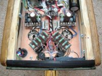
I have stripped the psu and rebuilt.
140uF 450V mallory cap to choke out of the scrap box just went inside 150mA (Pulling 135mA) -47uf +47uF Mcap(mundorf). Star Gnd. Heaters 220 Ohm to Gnd Hum bucking star connected.
Cathode feed back via output Tx works well. Bass can be very deep at times!
Working with slight hum and hiss with your ear to speakers.
sounds very good as first impressions!
Only just got it working going to tweek a bit!
Let you know how it progresses.
Regards
M. Gregg
Last edited:
Hi,
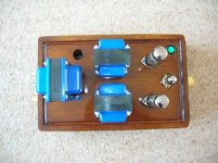
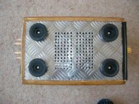
Just some photos of the project.
Needs some tidying up!
Top / bottom PSU mod etc. 🙂
Just for interest the chassis remains cool after 4 hours of music.
Only slight warmth of choke which is by the vent hole causes convection.
All components cool to the touch!
Chassis size is 220mm x 350mm x 67mm (external). Could not see how I could get it smaller!
Regards
M. Gregg
Attachments


Last edited:
Well done!
Glad to see it all worked out Ok.
Now you can sit back and enjoy it.
All the best
Henry
Glad to see it all worked out Ok.
Now you can sit back and enjoy it.
All the best
Henry
I agree, it looks fine and the lay-out looks technically well designed.
Is the hum problem now solved ?
And what became the schematic finally ?
This ?
Is the hum problem now solved ?
And what became the schematic finally ?
This ?
An externally hosted image should be here but it was not working when we last tested it.
I agree, it looks fine and the lay-out looks technically well designed.
Is the hum problem now solved ?
And what became the schematic finally ?
This ?An externally hosted image should be here but it was not working when we last tested it.
Yes it is this circuit, some small changes :
Input pot is 100k Log dual gang as shown in parts list previous post!
I have removed the 10K resistor and the 22uF cap on the power rail, The 150K on the 12ax7 anode goes to the main supply B+ same point as the output Tx B+. I could add it however it sounds very good as it is! No noise from 12ax7.
There is now no hum unless you put your ear nearly touching the speaker cone. I would tweek it however it is not off long enough.LOL🙂
Thank's to all who have input into this thread!
Regards
M. Gregg
I have removed the 10K resistor and the 22uF cap on the power rail
Don't do that. These components have hum attenuating effect in typical case.
There is now no hum unless you put your ear nearly touching the speaker cone
Strange ????
Don't do that. These components have hum attenuating effect in typical case.
I agree this is usually the case! However in this case there is no hum. I tried with it in place and the sound was not as good. Could have been the quality of cap for the 22uF. I have never had a problem with the 12ax7 stage and hum. This is the case up to full volume! I thought the back emf from the output Tx would be a problem but no problem has occured.
Regards
M. Gregg
Last edited:
Do you have any test equipment to measure max. ouput power and distortion ?
Also the frequency response would be interesting to know.
Also the frequency response would be interesting to know.
Agree with Arto, the 10K and 22uF should be there.
The lack of it would explain why you had so much hum with the 'simple' power supply. It reall should have no effect at all on the sound quality.
Henry
The lack of it would explain why you had so much hum with the 'simple' power supply. It reall should have no effect at all on the sound quality.
Henry
Agree with Arto, the 10K and 22uF should be there.
The lack of it would explain why you had so much hum with the 'simple' power supply. It reall should have no effect at all on the sound quality.
Henry
Hi,
When I used the simple power supply everything was as in the schematic.
I have only removed it since the rebuild. However I have a few things I want to try. I notice that I can get a cap at 600uF rating at 500V to fit the same size as the Mallory cap. Also I can get a choke with less DC resistance with lower inductance in the same frame size. So thoughts are to replace cap and choke. This should give less voltage drop across the choke (more head room and power). Then I will fit the 10K and a cap (keeps every one happy) LOL. I also want to try bypassing the choke with a cap, this has worked well in the past with improved clarity and seems to increase the high frequency response.
I only have a scope at the moment I could borrow a sig genny and do some measurements after I have done the mods. I only tend to check square and sine in the past so you will have to tell me what and how you want it measured. I guess things like a frequency set point and increase power till it clips.
I notice as I get the hum lower that I can hear the end bells of the power Tx resonate. very quite but it is there the side with the edcor sticker is quieter.LOL. It is not a shorted turn issue just one of those things! So I will remove and spray the inside of the end bells with carpet rubber glue. That will stop it! Its safe I have done it before. The Tx is cold to the touch warm after about 3 hours. Just me being fussy!🙂
Regards
M. Gregg
Last edited:
I could borrow a sig genny and do some measurements
You don't need to borrow. Here is one free signal generator + scope + spectrum analyzer.
TrueRTA Audio Spectrum Analyzer Software
- Status
- Not open for further replies.
- Home
- Amplifiers
- Tubes / Valves
- Any thoughts on this circuit?