Just for interest.
I came across this circuit has anyone ever used it?
The reason I ask is I am looking at a possible Miniwatt using inverter and 3 tubes 2x EL34 1x ECC81 just for fun!
🙂
Regards
M. Gregg
I came across this circuit has anyone ever used it?
The reason I ask is I am looking at a possible Miniwatt using inverter and 3 tubes 2x EL34 1x ECC81 just for fun!
🙂
Regards
M. Gregg
Attachments
Last edited:
Looks like the most basic tube amp. You find similar circuits/examples in texts and 1950's tube manuals.
paul
paul
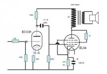
This is the circuit as shown.
Spec is supposed to be 3.5 W and it was used with Voight speakers.
So 3.5w per channel.
Here is the idea - link
http://www.miniwatt.com.hk/
Regards
M. Gregg
Spec is supposed to be 3.5 W and it was used with Voight speakers.
So 3.5w per channel.
Here is the idea - link
http://www.miniwatt.com.hk/
Regards
M. Gregg
Last edited:
This is the circuit as shown.
Spec is supposed to be 3.5 W and it was used with Voight speakers.
So 3.5w per channel.
Here is the idea - link
MiniWatt Tube Amplifier
Regards
M. Gregg
Pretty high distortion rating w/o feedback.
I agree that it resembles a lot of simple circuits, but I must be missing something...we've got signal in, ground, but where's the B+ connection?
Something overlooked in the drafting dept?
John
Something overlooked in the drafting dept?
John
I agree that it resembles a lot of simple circuits, but I must be missing something...we've got signal in, ground, but where's the B+ connection?
Something overlooked in the drafting dept?
John
Sorry,
The B+ is top of the Op Tx (5K) 225V 60mA.
Regards
M. Gregg
What's going on? The schematic you posted is of an ECC81 driving a triode strapped EL34. The Miniwatt amp you linked to (as inspiration?) is a 12AX7 driving an EL84, and it's definitely not triode strapped or it wouldn't make 3.5W. What are you trying to achieve?
What's going on? The schematic you posted is of an ECC81 driving a triode strapped EL34. The Miniwatt amp you linked to (as inspiration?) is a 12AX7 driving an EL84, and it's definitely not triode strapped or it wouldn't make 3.5W. What are you trying to achieve?
The idea is to get an "improved" miniwatt. Using triode EL34 to get the same output power.🙂
Or switchable pentode to get more power! If you have any improvements please post!
Last edited:
The idea is to get an "improved" miniwatt. Using triode EL34 to get the same output power.🙂
Or switchable pentode to get more power! If you have any improvements please post!
It's hard to talk in generalities since the devil is in the details, but one aspect is that a pentode EL84 is so much easier to drive than a trioded EL34 that you might be very well be taking a step backwards rather than forwards.
There are SO many choices out there. Have a look at the Simple SE for one.
Here is one with EL34:
An externally hosted image should be here but it was not working when we last tested it.
Here is one with EL34:
Do you have current demand of the circuit and output power?
Regards
M. Gregg
current demand is easy - its around 115ma through the EL34 and a smidge more for the driver. 250ma all up maximum for a stereo pair.
Power output is some 10 watts depending on the anode voltage you use.
If your supply voltage is close to 300 volts, then the cathode resistor of EL34 must be bigger, up to 200...220 ohms.
If your supply voltage is close to 300 volts, then the cathode resistor of EL34 must be bigger, up to 200...220 ohms.
Stupid newbie question: Why is the screen grid connected to the OPT center tap instead of the plate of the EL34?
..Todd
..Todd
Stupid newbie question: Why is the screen grid connected to the OPT center tap instead of the plate of the EL34?
..Todd
ultralinear
Why is the screen grid connected to the OPT center tap instead of the plate of the EL34?
When screen is connected this way, the circuit is called as ultra-linear.
This kind of circuitry gives low output impedance and good linearity like triode connection. It is also not very sensitive to load impedance variation and thus again resembles triode output stage.
On the other hand it has high(er) output power and requires less driving voltage like pentede connection.
According to some Mullard test report, UL-connection is more linear and produces less harmonic - and intermodulation distortion than triode connection.
Agree with Leadbelly, stick with EL84, but thats ne reason not to experiment with others, like 6BW6. Keep it in pentode mode but include the secondary winding in the EL84 cathode ciruit, ie remove the 1000uF neg end off the ground, attach it to secondary, with the other end of the secondary to ground. You'll have to experiment with this one as one way it will work and the other it will oscillate.
Regards
Henry
Regards
Henry
- Status
- Not open for further replies.
- Home
- Amplifiers
- Tubes / Valves
- Any thoughts on this circuit?