Built it a couple of years back.
As it happens I used a higher value of cathode resistor(470R) so as to be able to plug any valve in for comparison, the downside of this is just lower power output, but it means you can try different valves. When you decide on your preferred one then just put in the appropriate value for the valve and supply volts.
Artosolo is correct with 120R for the EL34.
With lots of different valves I couldn't really hear any significant difference between valves. My freind preferred a vintage Russian 6L6 (Brimar logo).
Which part of the country are you in?
regards
Henry
Ill send a PM.
What primary impedance of O/P Tx did you use on your build? Tx Make?
Regards
M. Gregg
What primary impedance of O/P Tx did you use on your build? Tx Make?
Regards
M. Gregg
Messages recieved, a bit too far to 'drop by'.
I used the OPT from a Ferrograph reel to reel machine. Also used it's power transformer. The machine unfortunately was a dead one with a very rusty mechanism.
Took the OPT from the audio chassis and mounted it on the PSU chassis.
I believe the transformers were of Partridge manufacture and intended for use with an EL84 and (going from memory) the primary impedance around 4K.
Messages recieved, a bit too far to 'drop by'.
I used the OPT from a Ferrograph reel to reel machine. Also used it's power transformer. The machine unfortunately was a dead one with a very rusty mechanism.
Took the OPT from the audio chassis and mounted it on the PSU chassis.
I believe the transformers were of Partridge manufacture and intended for use with an EL84 and (going from memory) the primary impedance around 4K.
Yes the "Partridge manufacture" Tx.
It will be interesting to hear how this sounds with Edcor Tx.
I will build for EL34 slightly higher power. I like the sound of KT66 I have some old CVC I think probably chinese by the look of them.
Should be quite interesting!🙂
Regards
M. Gregg
So the values of B+ are as stated 250-300V with 120 Ohm cathode resistor.
I would say that 120 ohms is only for 250 volts since the total current is already at the maximum. With 300 volts the cathode resistor must be bigger.
It is better to beging with lower anode current and then increase it if the power output is not sufficient or distortion too high.
I would also recommend you to build the original circuit with global NFB and then compare these two.
Just for interest,
I have sent the order for 2X 15W 8Ohm 2.5k Op Tx and 1X power Tx. To Edcor.
Shipping at checkout was $69 to UK (10Watt Tx would have been cheaper).
I will let you know how it goes.
Everyone have a good Christmas. Catch you later!
Regards
M. Gregg
I have sent the order for 2X 15W 8Ohm 2.5k Op Tx and 1X power Tx. To Edcor.
Shipping at checkout was $69 to UK (10Watt Tx would have been cheaper).
I will let you know how it goes.
Everyone have a good Christmas. Catch you later!
Regards
M. Gregg
Last edited:
Hi M Gregg.
Any progress on this project?
Regards
Henry
Still waiting for the Tx's to arrive. Edcor did not work over Xmas period so there is a 5 week wait.🙂
Regards
M. Gregg
Edcor to UK
Just for interest,
Tracking of Tx's from Edcor to UK.
Payment after customs was £30.00.
So the total for 3 X transformers "2x output 15W and 1X power Tx came to £134.00. all in total cost.
This might be of interest for anyone thinking of buying in the UK.
This is linked to the delivery in orange below!
Detailed Results:
At this point I could not work out what was happening, I found out that USPS transfer to Parcel Force to deliver in the UK and the number changes. So the Delivered abroad means to Parcel Force not the customer. If I had waited Parcel Force send a request for the customs payment. It reads from bottom to top!
So I will start collecting components for the build.😀
I have received the Tx's!
Regards
M. Gregg
Just for interest,
Tracking of Tx's from Edcor to UK.
Payment after customs was £30.00.
So the total for 3 X transformers "2x output 15W and 1X power Tx came to £134.00. all in total cost.
This might be of interest for anyone thinking of buying in the UK.
This is linked to the delivery in orange below!
Detailed Results:
At this point I could not work out what was happening, I found out that USPS transfer to Parcel Force to deliver in the UK and the number changes. So the Delivered abroad means to Parcel Force not the customer. If I had waited Parcel Force send a request for the customs payment. It reads from bottom to top!
An externally hosted image should be here but it was not working when we last tested it.
An externally hosted image should be here but it was not working when we last tested it.
An externally hosted image should be here but it was not working when we last tested it.
Delivered Abroad, January 25, 2011, 2:02 pm, GREAT BRITAINAn externally hosted image should be here but it was not working when we last tested it.
Attempted Delivery Abroad, January 22, 2011, 6:58 am, GREAT BRITAINAn externally hosted image should be here but it was not working when we last tested it.
At Foreign Delivery Unit, January 22, 2011, 12:06 am, GREAT BRITAINAn externally hosted image should be here but it was not working when we last tested it.
Out of Foreign Customs, January 21, 2011, 10:39 am, GREAT BRITAINAn externally hosted image should be here but it was not working when we last tested it.
Into Foreign Customs, January 20, 2011, 9:23 am, GREAT BRITAINAn externally hosted image should be here but it was not working when we last tested it.
Into Foreign Customs, January 20, 2011, 9:22 am, GREAT BRITAINAn externally hosted image should be here but it was not working when we last tested it.
Arrived Abroad, January 20, 2011, 9:18 am, GREAT BRITAINAn externally hosted image should be here but it was not working when we last tested it.
International Dispatch, January 16, 2011, 5:05 pm, ISC LOS ANGELES CA (USPS)An externally hosted image should be here but it was not working when we last tested it.
ArrivalAn externally hosted image should be here but it was not working when we last tested it.
Processed through Sort Facility, January 13, 2011, 3:59 pm, CARLSBAD, NM 88220An externally hosted image should be here but it was not working when we last tested it.
Electronic Shipping Info Received, January 12, 2011So I will start collecting components for the build.😀
I have received the Tx's!
Regards
M. Gregg
Last edited:
Hi again.
Interesting development.
Just had a Pye Mozart amp in for a checkup.
It is a single ended EL34 stereo amp giving 10 Watts.
It also has the 15 Ohm output winding in the EL34 Cathode circuit. The cathode bias resistor is 150R.
What is also really interesting is it has an extra secondary winding, giving 10% of the 15R winding, and this is connected, in antiphase, to the cathode of the driving valve (ECC83).
There is no other feedback.
Henry
Hi again.
Interesting development.
Just had a Pye Mozart amp in for a checkup.
It is a single ended EL34 stereo amp giving 10 Watts.
It also has the 15 Ohm output winding in the EL34 Cathode circuit. The cathode bias resistor is 150R.
What is also really interesting is it has an extra secondary winding, giving 10% of the 15R winding, and this is connected, in antiphase, to the cathode of the driving valve (ECC83).
There is no other feedback.
Henry
Hi,
Yes I have looked at the PYE circuit it has some similarities. I have started the chassis and collected a few components. I will post some pics when I start the build. Been a bit tied up. 🙂
components:
4 x(SUPS0-070) - 0.1uF 1200V M Cap Supreme silver/oil Caps1 xTKD 2CP-601 100K dual log taper potentiometer2 x(RES-2K170) - 220R 2W Kiwame Resistor2 x(REY75-670) 680K - 1W Takman Metal Film Resistor2 x(REY75-450) 10K - 1W Takman Metal Film Resistor2 x(RES-M1270) - 120R 12W MRA12 Mills Resistor2 x(REY75-340) 1K2 - 1W Takman Metal Film Resistor2 x(REY75-590) 150K - 1W Takman Metal Film Resistor2 x(ELNAS-132) - 220uF 50V Elna Silmic II Electrolytic Capacitor2 x(REY75-690) 1M - 1W Takman Metal Film Resistor2 x(RES-M1290) - 220R 12W MRA12 Mills Resistor2 xAudio Note octal Alumina, chassis mount base (VBASEUX8)1 xCardas`s quad eutectic solder, 100g reel
Regards
M. Gregg
I suppose you mean this:
http://www.audiofaidate.org/uploaded/plovati/PyeMozart10.JPG
I think there is also an other feedback loop from the cathode of EL34 to cathode of 1st ECC83 stage.
But what is RV2 for ?
http://www.audiofaidate.org/uploaded/plovati/PyeMozart10.JPG
I think there is also an other feedback loop from the cathode of EL34 to cathode of 1st ECC83 stage.
But what is RV2 for ?
I suppose you mean this:
http://www.audiofaidate.org/uploaded/plovati/PyeMozart10.JPG
I think there is also an other feedback loop from the cathode of EL34 to cathode of 1st ECC83 stage.
But what is RV2 for ?
Reminds me of the fisher bias circuit!
Regards
M. gregg
Last edited:
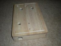
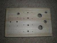
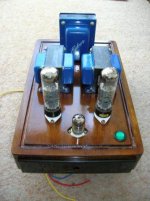
Just thought I would show a shot of the chassis with the front plate not fixed yet!🙂
Still a lot of work to do!
Just for interest notice no holes around the tubes.
There is a 3mm gap around the ceramic tube bases when mounted.
Regards
M. Gregg
Still a lot of work to do!
Just for interest notice no holes around the tubes.
There is a 3mm gap around the ceramic tube bases when mounted.
Regards
M. Gregg
Attachments

Last edited:
Looks very nice. 🙂Just for interest notice no holes around the tubes.
How do you plan on getting the heat from cathode resistors and whatnot out from under the chassis? I would expect there will be toasting hot down there with an all wood chassis, unless you have something sneaky up your sleeve.
- Frank.
Morning all.
Arto, you are correct, there is another feedback loop, but the circuit I have copied from the amp here is slighly different.
The point 'O' from the OPTx goes straight to ground.the 15R tap goes to the cathode via a150R resistor bypassed by a 200uF cap.
R3 is now 120K and in series with a 1uF cap.
R2 is now 44M (2 x 22M in seies) I believe this is a hum cancel device.
R10 goes straight to ground and RV2 does not exist.
There is no fixed bias and R4 goes to ground.
R17 is 270K.
The circuit I have is from the stereo Mozart. The one you show looks to be the mono version?
Regards
Henry
Thanks for additional details.
Altogether this seems interesting circuit and obviously it gives all that EL34 SE can provide.
Altogether this seems interesting circuit and obviously it gives all that EL34 SE can provide.
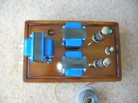
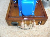
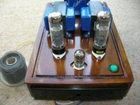
Just some more progress,
A bit slow due to hectic schedule at work!
Tube sockets are mounted on silicone washers.
The finish was a moment of madness French Polish.
Still a lot to do!
The chassis is screened with EMI tape and foil.
due to the input being single L&R phono these are Rhodium.
(Looked for unobtainium could not find any).
Base is aluminium checker plate!
All Tx's are mounted on silicone pads.
Speaker terminals are gold plated red copper.
Just a post so you know I'm not slacking.🙂
Regards
M. Gregg
Attachments
- Status
- Not open for further replies.
- Home
- Amplifiers
- Tubes / Valves
- Any thoughts on this circuit?