1khz Square wave at +- 2.5vIt's a pity, the amplifier sounds exactly like adjusting the frequency compensation.
Selecting the necessary operating currents and topology is easy and not always decisive.
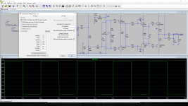
Turn off C1 at the input and apply a meander - this circuit should keep the amplifier in a stable state, i.e. the meander at the output must be free of emissions, you can also additionally check with a 1 kHz sine wave at the maximum input amplitude voltage.
Attachments
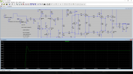
Is C5 the input coupling capacitor? It can take very long to settle unless you give the pulse source a negative delay of minus half its rise time, so that it starts with a voltage halfway the positive and negative peaks. Just removing the capacitor is also fine.
To check small signal stability, you would have to run the simulation with a smaller square wave with shorter rise and fall times, say 10 mV peak-peak and 100 ps rise and fall times. Then check the output waveform before the output filter.
If that looks good, then you can check what happens with larger square waves or when you drive it into clipping with a big sine.
A square wave with a frequency of 1 kHz is not sufficient to visually examine the surge at the front of this meander; 20 kHz is required.1khz Square wave at +- 2.5v
And the fact that there is an overshoot (in your picture) indicates insufficient amplifier correction.
*C4 needs to be damped with a resistor, you don't have a modulated signal in the amplifier that needs to be filtered at the output.
*Due to overshoot in insufficient speed in the feedback circuit, an accelerating capacitor is needed, its value is calculated according to Bouche equation.
*C15 of such a large denomination should be placed directly on the bases of the output power transistors, and not on the emitters of the previous stage.
*The low stability of the circuit for direct voltage will not give you the opportunity in practice to connect the circuit without a coupling capacitor at the input and a capacitor in series with the resistor R22 in the feedback circuit.
Last edited:
C5 is in the feedback network , gain. 20k / 1k 100uf to ground 20x gain. Removing the cap " solved" it .Is C5 the input coupling capacitor? It can take very long to settle unless you give the pulse source a negative delay of minus half its rise time, so that it starts with a voltage halfway the positive and negative peaks. Just removing the capacitor is also fine.
To check small signal stability, you would have to run the simulation with a smaller square wave with shorter rise and fall times, say 10 mV peak-peak and 100 ps rise and fall times. Then check the output waveform before the output filter.
If that looks good, then you can check what happens with larger square waves or when you drive it into clipping with a big sine.
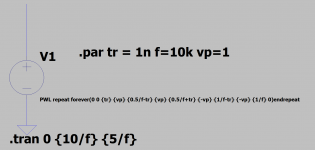
About the square wave symmetry. There is no simple way to define a spice "pulse" voltage source that is suitable for an audio amplifier input. The problem is that the time zero voltage needs to be zero but with both positive and negative pulses, and the pulse definition does not include a midway voltage or time. The best way is with a PWL wave definition as attached.
Attachments
- Home
- Amplifiers
- Solid State
- Any thoughts about this?