Ok, so last night I rambled on a bit, and also mentioned that I would explain why I am eager to get these little amps up and running again.
Sooo... Way back, my original setup was a Rega Planar3, fitted with an Ortofon VMS20E mkII Cartridge, A Trio KA305 Amp but with the Pre Amp driving the Maplin Amps, and a pair of Goodmans Magister Loud speakers (15" Bass units), The speakers were on stands about 12" - 15" off of the floor.
Three album tracks that sounded incredible spring to mind.
Pink Floyd's "Hey You" from The Wall, The acoustic guitar at the beginning, seemed to float in the air above the speakers (No I wasn't High) 🙂
Judie Tzuke's "For You" from the album Welcome to the cruise, The string quartet, I was able to place each and every instrument within the sound stage.
Al Stewart's "Midas Shadow" from the album Year of the cat, Part way through the song there are some Maracas (Shakers) used, The only way to describe the effect is it was like there was someone in the room shaking them, and totally separated from everything else.
These are the things I'm looking to get back.
A lot has changed, I now have a pair of B&W 602 Speakers, and probably not situated in the best position at the moment.
The Source is CD from a Panasonic CD Player, and the Quad Mono Blocks, with the 22 control unit, which in my opinion isn't a great pre amp.
I listened to the CD version of "Al Stewarts" Year of the cat the other day, and everything just seems muddied together, and the Maracas I mentiond just buried in the background, It was actually quite fatiguing to listen to.
I do need to repair the antiskate Adjustment belt on the Rega before I put any of my beloved vinyl on it, I made the mistake of giving the Antiskate control a wiggle after getting the turntable out of hibernation, and the belt snapped at the Max (3) position.
Sorry if most of this doesn't really belong here, but I hope it gives an idea of how good these amps can actually sound 🙂
Last edited:
No kidding. Almost none.Evidence that Maplin didn't spend much time developing the design
And the Hitachi is a primitive design in an application note. Semiconductor manufacturers are really good at making transistors but their application notes are not filled with expert audio designs. So I wouldn't be too precious about their part choices. 😉
The dilemma is whether to maintain the original topology and just do a better job of it or whether to redesign it. The latter opens up a wide set of solutions so I've been focusing on the former.
I don’t think this is true at all. Some of the linear tech app notes advanced the state of the art considerably. Case in point being their AN67 low distortion oscillator. This amp, simple as it is, provides quite good performance and shows how the mosfets need no thermal compensation.
I empathize completely. I also have a Rega Planar 3 but I don't use it anymore. It took the Mark Levinson No39 to beat it and that's what I use now. I don't know which Panasonic CD player you use but if it's old it is going to sound crap. Sorry. Probably not as bad as my iPhone 6S (which really "p"s me off). I'm not familiar with either speaker.Sorry if most of this doesn't really belong here, but I hope it gives an idea of how good these amps can actually sound 🙂
Having an excellent front end for an amp is very important...more so than similarly priced speakers. You can have the best amp and speakers in the world but it's still garbage in garbage out. Digital sources can be so so bad. Having said that, a lot of amps really kill music so you have to choose carefully.
The Maplin circuit sounds quite good for what it is. I recall it sounding smoothly musical. One Maplin board is likely to sound a little different from another. I used to use my own variant of it many years back and this thread is a bit nostalgic. I am confident the changes you are making now will make it sound better whilst maintaining the original topology. Just how much difference these will make is hard to predict. Some of my recommendations are are a bit audiophile...but they won't make it worse. 🙂
I agree there are some fine app notes. I have not seen a discrete audio power amplifier in any application note that is anything but a crude starter circuit to illustrate the use of a component being sold. Invariably a lack of attention to detail. But that's not what an application note is for, after all.I don’t think this is true at all. Some of the linear tech app notes advanced the state of the art considerably. Case in point being their AN67 low distortion oscillator. This amp, simple as it is, provides quite good performance and shows how the mosfets need no thermal compensation.
Last edited:
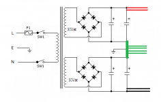
Yep. It shouldn't be implemented like the schematic shows.That layout shows the Speaker Return tapping into the Centre tap of the Transformer/PSU.
DiyGazza has his star ground between the supply caps: post #19. How the transformer secondaries and rectifier bridge(s) are wired hasn't been revealed yet.
I agree about some excellent ones from LTC, AD and of course Nat Semi.I agree there are some fine app notes...
Many other companies clearly passed writing Application Notes to the intern.
If a short blew a couple of outputs, more device sales for Hitachi and it was never good marketing to emphasize that the mighty mosfet needed SOA protection
Yep. It shouldn't be implemented like the schematic shows.
DiyGazza has his star ground between the supply caps: post #19. How the transformer secondaries and rectifier bridge(s) are wired hasn't been revealed yet.
Ooop's ....The Transformer secondary centre taps ARE connected to the smoothing caps 0v, and then to mains ground, AC from each winding goes to the Bridge Rectifier and the +/- to either side of the Caps.
I can see more mods on the way

I don't know which Panasonic CD player you use but if it's old it is going to sound crap. Sorry. Probably not as bad as my iPhone 6S (which really "p"s me off).
Yeah, It's old, Panasonic SL-PG590, probably get one on eBay for a fiver 😀
So your transformer has two centre-tapped secondaries, each 35-0-35?
And they both have a bridge rectifier whose outputs are connected in parallel to the supply caps?
Ok. Why did you use two rectifiers rather than paralleling the secondaries and using one rectifier?
And they both have a bridge rectifier whose outputs are connected in parallel to the supply caps?
Ok. Why did you use two rectifiers rather than paralleling the secondaries and using one rectifier?
Last edited:
So your transformer has two centre-tapped secondaries, each 35-0-35?
And they both have a bridge rectifier whose outputs are connected in parallel to the supply caps?
Ok. Why did you use two rectifiers rather than paralleling the secondaries and using one rectifier?
No, Perhaps I didn't word that very well.
1 Transformer, with dual secondaries wired in series to form the centre tap in the middle, the other ends of the windings go to (One) Bridge rectifier, the +/- from the rectifier go to the +/- of the smoothing caps, I have the centre tap of the transformer connected between the caps to form the 0v.
Does that make sense?
Oh and the CD Player is a Technics, not a Panasonic, One of those days .....
Ok, I see. The problem I think Andrew was talking about is that of high capacitor charging currents flowing through the star ground and causing some ground bounce.
One way to avoid this is to make two separate supplies and join them in series. Each secondary winding goes to its own bridge and then from the bridge to its own capacitor. Or in your case to its own pair of paralleled capacitors. Then you join them in series with your star ground wire. The charging currents only go through the capacitors.
How big are your supply caps?
A simpler way is to keep what you’ve got but join the windings at a new point separate to the star point and run two wires from here to each capacitor. Thus the charging currents go through a separate path and not through the star ground.
I’m not certain this is a cure...I’ll ponder.
I’m not certain this is a cure...I’ll ponder.
Last edited:
Ok, I see. The problem I think Andrew was talking about is that of high capacitor charging currents flowing through the star ground and causing some ground bounce.
One way to avoid this is to make two separate supplies and join them in series. Each secondary winding goes to its own bridge and then from the bridge to its own capacitor. Or in your case to its own pair of paralleled capacitors. Then you join them in series with your star ground wire. The charging currents only go through the capacitors.
How big are your supply caps?
Yay, Internet Back .... Been off most of the day....
Still not sure I fully understand that, but if it means adding more caps and another Bridge Rectifier, this is where I would have to call it a day, The Case is very compact, and as it is I only just managed to squeeze everything in. It would mean starting over with a new and bigger case.
The caps are 4 x 6800uf, - 13,600uf per rail.
I should have a new 30v - 0 - 30v 300va Toroid arriving tomorrow, along with some 8.2k 1 watt resistors (R9) I already have the 33k resistors for R2, which I will fit when I change the transformer and R9, Hopefully that will help bring down the DC Offset a bit.
This is better just needs one bridge.
An externally hosted image should be here but it was not working when we last tested it.
@Nigel. That is simpler. Can you arrange it so that no supply cap charging current flows through the star ground point?
Yes.Like This ?
Attachments
Last edited:
- Home
- Amplifiers
- Solid State
- Any Maplin MosFet Amp Guru's on here?