Agreed. I'm very glad there has been so much interest in this great amp, I remember traderbam's reaction when I first showed him the schematiche appears to have now seen the light.........😎
 😀
😀My pcb software allows drill holes without pads on the top of the pcb so they don't short out on mounting bracket.
Yes, Still not had chance to have a good play around with that yet, but I can see in the not too distant future it may very well be put to very good use 🙂
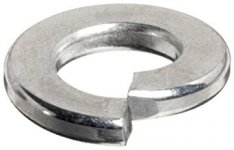
Consider using these washers when mounting T03s SPRING CONICAL THICK WASHERS FLAT WASHER A2 STAINLESS STEEL DIN 6796 M3 TO M24 | eBay in fact anywhere there is expansion and contraction due to heat
In the original article it tells you to use shake proof washers, then a couple of days ago I was reading an article regarding the mounting of T03's and it tell you NOT to use shake proof or spring type washers, but use their special (Collapsible Washers) ... I Think, which should be tightened to a certain torque 😕
But if that's what you're using and they do the job, that's good enough for me 🙂
Have a look at this...belleville washer..the conical spring washer was the nearest I could find that is easily attainable http://www.ti.com/lit/an/sboa020/sboa020.pdf
Belleville washer - Wikipedia
Belleville washer - Wikipedia
Last edited:
Have a look at this...belleville washer..the conical spring washer was the nearest I could find that is easily attainable http://www.ti.com/lit/an/sboa020/sboa020.pdf
Belleville washer - Wikipedia
Aha, I believe that was the very documentation I was reading, and thought the washer was one of their own parts, so looks as though in practice the right size conical washer will do the job just fine.
There is no point in designing for single sided these days. Making your own PCB is just not worth the hassle with corrosive chemicals and the double sided PTH makes soldering much more reliable. The cost difference between single and double sided is negligible unless you are into throw away consumer devices.
That layout shows the Speaker Return tapping into the Centre tap of the Transformer/PSU.This explains why R2 is 47k, Should R7 also possibly be 47k?
Never take any audio references to the Centre Tap.
Form the transformer to rectifier connections with very short and very low loop area wiring.
Form the Rectifier to smoothing cap connections with very short and very low loop area wiring.
Bring the Centre Tap along, or twisted, with the transformer wires past the rectifier and twisted with the rectifier to smoothing cap wires.
Then take a 3 wire twisted triplet from the smoothing capacitors to the load.
If you are building stereo then take a second twisted triplet from the smoothing capacitors to the other load.
The speaker return must be taken to the Main Audio ground (MAG). This will be on the PCB in a mono build, or adjacent to the two PCBs in a stereo build.
That MAG is also the Return for other amplifier currents and becomes "star like".
Caution is for wimps. The 12k is dissipating just under half a watt with 50V rails. 8.2k will dissipate under one third of a watt so a 1W resistor will be fine. If you drop the supply to 42V then the 8.2k will dissipate about 200mW.@ traderbam R9, the 12k, Yes it does get very hot, and I think if I replace it I would be tempted to go for a 2 watt, I believe there is enough room to squeeze one in, I'm a little cautious of dropping the value of R9 to 8.2k and into the amps with the original Hitachi Fets, thats why I was hoping to get hold of a couple more PCB's and fit the Exicon Fets, they are a lot cheaper to replace should something misbehave.
42V is fine. 30-0-30 300VA ok.After reading all of the posts, I think I should really consider dropping the Power suppy rails to +/- 40v, although a the closest transformer I can get from RS is 30v - 0 - 30v, Ideally I would need a transformer with 28v secondary's to give the 40v rails, would we still also be looking at 300va for a pair of amps?.
Actually I think I may have of these spare. Let me check.
No, you are better off making R2=33k. That way you maintain the same feedback loop gain. 33k is perfectly fine for the input.This explains why R2 is 47k, Should R7 also possibly be 47k?
Why Goodman chose 47k is unclear from the article; probably to conform with some convention at the time: 47k + 2.2k = 50k approx.
For mounting power transistors:
Attachments
Last edited:
I agree. Use eye protection when building one of these.Agreed. I'm very glad there has been so much interest in this great amp, I remember traderbam's reaction when I first showed him the schematic
30V will be at 230V and full load. Factor in >250V as found in many places and lighter load and you could easily be +15% on that, which would give 47V after the bridge.42V is fine. 30-0-30 300VA ok.
Actually I think I may have of these spare. Let me check.
If you live in a high mains area, think about using a 9-0-9 25VA as a bucking transformer to drop the voltage across the big toroid to 230V.
30V transformer is OK. Voltage will sag a little under the load at full power so you'll have just about 40VDC. (Magnum amp used 35V transformer).
Interesting, I had heard that the Maplin design was based on the Hitachi Application Notes, but had never seen them, They really are so alike !
The Hitachi version also has DC imbalance. 100mv offset was considered perfectly reasonable back then, these days even a tenth of that is frowned on by some.
30V will be at 230V and full load. Factor in >250V as found in many places and lighter load and you could easily be +15% on that, which would give 47V after the bridge.
If you live in a high mains area, think about using a 9-0-9 25VA as a bucking transformer to drop the voltage across the big toroid to 230V.
The mains in this area can be a bit "Wild" 238v at the moment, but during certain times of the day can vary from anywhere between 230 possibly a little lower on the odd occasion, and as high as 256v late at night for a brief period, generally though its around 245v.
My Main UPS is the AC Re Generation type, so will switch to its own inverter, without using the batteries should the voltage drop below 229v or over 251v, but doesn't switch over very often, It logs these events so that's how I know how much the voltage varies, I don't do DVM Watching all day 😀
Evidence that Maplin didn't spend much time developing the designInteresting, I had heard that the Maplin design was based on the Hitachi Application Notes, but had never seen them, They really are so alike !
That layout shows the Speaker Return tapping into the Centre tap of the Transformer/PSU.
Never take any audio references to the Centre Tap.
Form the transformer to rectifier connections with very short and very low loop area wiring.
Form the Rectifier to smoothing cap connections with very short and very low loop area wiring.
Bring the Centre Tap along, or twisted, with the transformer wires past the rectifier and twisted with the rectifier to smoothing cap wires.
Then take a 3 wire twisted triplet from the smoothing capacitors to the load.
If you are building stereo then take a second twisted triplet from the smoothing capacitors to the other load.
The speaker return must be taken to the Main Audio ground (MAG). This will be on the PCB in a mono build, or adjacent to the two PCBs in a stereo build.
That MAG is also the Return for other amplifier currents and becomes "star like".
I did what traderbam suggested in post #48 😕
Hello ... PM sent
Also the BK mosfet amplifier modules Modules
are similar to the reference design that Maplin used in their kits. I have made a few of these and have better hum rejection and lower output offset.
Also for the maplin amplifier module I have used the JLH mosfet amplifier power supply regulation module with exellent results .. A Paul Kemble web page - JLH mosfet amplifiers.
Hello ... PM sent
Also the BK mosfet amplifier modules Modules
are similar to the reference design that Maplin used in their kits. I have made a few of these and have better hum rejection and lower output offset.
Also for the maplin amplifier module I have used the JLH mosfet amplifier power supply regulation module with exellent results .. A Paul Kemble web page - JLH mosfet amplifiers.
Intersting, Thank you.
- Home
- Amplifiers
- Solid State
- Any Maplin MosFet Amp Guru's on here?