Speaker fuses are always an option and can be incorporated within the feedback loop. Sized correctly they offer great protection.
I was told that speaker fuses are a waste of time as the transistor blows before the fuse does.
However, I had added a fuse to the output of my amp.
I tripped over a jack plug speaker lead and it came out of the socket.
It shorted on the way out and luckily only blew the fuse.
I quickly changed the fuse and carried on with the gig.
Speaker fuses can protect the transistors if the design has basic electronic protection. Reading the Maplin article at the start of this thread, the design was not originally meant to be 50V rail/100W and with 40V rail and suitable zener clamps, should survive before a fuse blew.
To me, it looks like the push to 50V was not fully thought out
To me, it looks like the push to 50V was not fully thought out
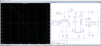
I found very little difference using a CCS to the pos PSRR. However, the common mode gain is greatly reduced. Using a big cap to short the bases is a little bit of a hack but it's good enough to show the difference and avoids having to mess with the big dc offset had I used a buffer to connect them and preserve the impedance at the inverting input. I think only the difference is informative not the absolute values because shorting the bases messes with the feedback loop gain.
Attachments
Last edited:
It is both. The collector of Q3 (in my model) is effectively connected to the pos supply. When I isolate it AND use a CCS for the input LTP the PSRR improves.Would the worse +Rail PSRR be due to not using CCS at the first LTP and/or C5?
Attachments
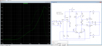
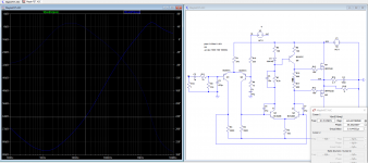
My simulations of the original, with the input grounded (not HiZ as above), show that the CCS resistor R3 causes poor LF +ve supply PSRR. This means 100Hz hum with sensitive speakers.
Adding any form of filtering eg a zener removes this, but still leaves poor LF -ve supply PSRR
Adding any form of filtering eg a zener removes this, but still leaves poor LF -ve supply PSRR
I just simulated the amplifier in ltspice.
Pretty much anything I did didn't start oscillation.
I removed gate stoppers and second ltp capacitors and no effect at all.
Even removed decoupling.
Simulations are fine up to a point but the only real test is a real pcb.
Pretty much anything I did didn't start oscillation.
I removed gate stoppers and second ltp capacitors and no effect at all.
Even removed decoupling.
Simulations are fine up to a point but the only real test is a real pcb.
Last edited:
It is both. The collector of Q3 (in my model) is effectively connected to the pos supply. When I isolate it AND use a CCS for the input LTP the PSRR improves.
Oh, that was quite some improvement, much more than I had anticipated for.
It's quite interesting seeing the Q5 base referenced to the driver side instead of being tied to GND, but apparently it works. 🙂
I was told that speaker fuses are a waste of time as the transistor blows before the fuse does.
Very true in a lot of cases, particularly for massive overloads.
Correctly sized fuses can save speakers though, and they can protect against moderate misuse such as running close to max output, a situation that is survivable short term.
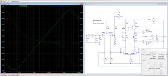
This is my latest interpretation for single die devices and 40V rails
Input impedances ac and dc balanced - improves offset and PSRR
Input LTP current constant source
Diodes across the first LTP make clipping better behaved
Common base in current mirror
Current mirror reduced to 6mA to allow TO-92 devices safely
Zener clamps on output device gates
Improved feedback compensation
Attachments
![2017-10-01 16_14_37-[ MaplinV2 _].png](/community/data/attachments/585/585945-07affaef45e20dd17d687164a6390d43.jpg?hash=B6_670XiDd)
Wow, This thread has really gone way beyond what I ever expected, and as I have been away for the last few days, you can imagine my surprise to see all of the posts that I have missed since I was last here on Thursday.
Some great issues and fixes raised, some really good intuitive simulations and analysis performed, and proposals for modifications to make the and not only more stable, but also more robust and reliable.
Not sure I agree with the user who said they were rubbish, and should just build something decent, I am sure that there are many people who have built these, and would agree that they are what they are, and despite the flaws they have still "Just Work" and pretty well at that.
It's a shame that "Jamesfeline" who claimes to have the Gerber Files for the original PCB has not responded or replied to my PM, as I would be interested in building one maybe two, using the Exicon ECF10N20 and ECF10P20 Output Fets, Looks like I'm going to have to brush up on my CAD and PCB Layout skills.
@ Mooly Have you run any simulations of the circuit in your last post?
@ nigelwright7557 Do you have a rough idea how much I might cost to get say 4 pcbs manufactured?
@ traderbam R9, the 12k, Yes it does get very hot, and I think if I replace it I would be tempted to go for a 2 watt, I believe there is enough room to squeeze one in, I'm a little cautious of dropping the value of R9 to 8.2k and into the amps with the original Hitachi Fets, thats why I was hoping to get hold of a couple more PCB's and fit the Exicon Fets, they are a lot cheaper to replace should something misbehave.
After reading all of the posts, I think I should really consider dropping the Power suppy rails to +/- 40v, although a the closest transformer I can get from RS is 30v - 0 - 30v, Ideally I would need a transformer with 28v secondary's to give the 40v rails, would we still also be looking at 300va for a pair of amps?.
Lastly, for the moment at least, should a redesign come to light, would a single layer PTH PCB be better or a Dual or even multi layer PCB using SMD components where possible be more suitable?
Well I've probably rambled enough 🙂 Totally shattered from a long drive, but I do have some more things I would like to mention, and although probably not really suited to the "Solid State" thread, they are in keeping of why I am so eager to see these little amps up and running again.
Oh and one more thing "Mooly" the component models that you use in LTspice, are they all contained within the free version, or do you need to purchase / Download any that are slightly obscure?
Cheers Guys and Gals
Last edited:
Agreed. I'm very glad there has been so much interest in this great amp, I remember traderbam's reaction when I first showed him the schematic  he appears to have now seen the light.........😎
he appears to have now seen the light.........😎@ nigelwright7557 Do you have a rough idea how much I might cost to get say 4 pcbs manufactured?
Cheers Guys and Gals
I use China PCB Prototype & Fabrication Manufacturer - PCB Prototype the Easy Way as they are good quality, cheap and usually very fast. For 10 off 10cm by 10cm pcb's it will be around $30
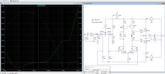
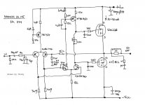
I managed to dig out my own version of the Maplin mosfet amp.
1/ 2 transistor CCS on front end.
2/ Two transistor current mirror.
3/ Slightly larger capacitors on 2nd LTP.
4/ RC decoupling on front end.
5/ Uses up to date ALFET lateral mosfets.
6/ zeners across GS on mosfets.
No hum, no oscillation and great sound.
1/ 2 transistor CCS on front end.
2/ Two transistor current mirror.
3/ Slightly larger capacitors on 2nd LTP.
4/ RC decoupling on front end.
5/ Uses up to date ALFET lateral mosfets.
6/ zeners across GS on mosfets.
No hum, no oscillation and great sound.
An externally hosted image should be here but it was not working when we last tested it.
Last edited:
That might be good news in a way because The mismatch between R2 & R7 should cause an excess positive dc offset. So it might be measuring as expected now. The fix is to try 33k for R2.
Why it was designed with R2 different from R7 is not clear to me. There must have been a reason.
This explains why R2 is 47k, Should R7 also possibly be 47k?
Attachments

I use China PCB Prototype & Fabrication Manufacturer - PCB Prototype the Easy Way as they are good quality, cheap and usually very fast. For 10 off 10cm by 10cm pcb's it will be around $30
Great, Thank you, That's not a bad price at all, I like the idea of using T03 type transistors, somehow seem more robust than the plastic types, even if they are a bit more of a pain to mount 🙂
Consider using these washers when mounting T03s SPRING CONICAL THICK WASHERS FLAT WASHER A2 STAINLESS STEEL DIN 6796 M3 TO M24 | eBay in fact anywhere there is expansion and contraction due to heat
Great, Thank you, That's not a bad price at all, I like the idea of using T03 type transistors, somehow seem more robust than the plastic types, even if they are a bit more of a pain to mount 🙂
I use the pcb as a drill template.
Just drill through pcb with drill same size as hole into mounting bracket to locate right positions. Then drill mounting bracket with right sized holes.
I usually start with an extra 4mm hole at either end so I can bolt a m3 bolt through to hold pcb in set position.
My pcb software allows drill holes without pads on the top of the pcb so they don't short out on mounting bracket.
Last edited:
- Home
- Amplifiers
- Solid State
- Any Maplin MosFet Amp Guru's on here?