That's an interesting JFET... Might be interesting to try them in a high voltage transformer coupled design in place of a pentode.
btw, i purchased 16n20d2 fro UT Source out of HongKong, i got enhancement mosfets instead....so be carefull...and the funny thing was, somebody sent me a message warning me but i did not listen, mea ultima culpa...
I haven't sent power through them yet, but I got them from mouser so I assume all will be well.
good luck, next time i will get those from mouser as well..the potential for using them is indeed promising..
Last edited:
Silicon carbide JFETs do not shine as an amplifier. What they are good at is switching large amounts of power.

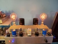
nice amp, what is the cold resistance of the lamps? and what is your standing bias on the mosfet?
You apply the gate-source voltage prior to the drain-source voltage, right? What is the purpose of the relays?
The cold resistance is 4R3. I have some 500W bulbs on the way to try, too.
The standing current is (I'm guessing) 1.5A or so? I'd have to measure it but it's hard to flip over with the bulb in it LOL I just set it for 25V at the drain. If I tie gate to source (and turn ON the MOSFET), it's about 1.8A.
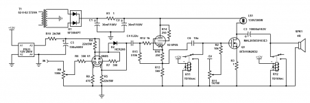
The first relay grounds the gate while the tube warms up (it can spike 140V until the cap charges up and I didn't have zeners to limit Vgs. The second one grounds the speakers on power on to get rid of the "thump".
The standing current is (I'm guessing) 1.5A or so? I'd have to measure it but it's hard to flip over with the bulb in it LOL I just set it for 25V at the drain. If I tie gate to source (and turn ON the MOSFET), it's about 1.8A.
The first relay grounds the gate while the tube warms up (it can spike 140V until the cap charges up and I didn't have zeners to limit Vgs. The second one grounds the speakers on power on to get rid of the "thump".
Why three? All the relays are tied to the same time delay. I might replace the relay with anti-series zeners to protect the MOSFET to free up the sockets for use as cathode followers to try and get better HF out of it.
Not allowing the tubes to warm up before applying the B+ voltage and applying the drain-source voltage before the gate-source voltage is present are equally harmful. My solution would be three manual switches. No relays, no protective diodes, no current spikes, no stress on devices, no thumps.
I'm personally not fond of voltage followers. Expect very low bandwidth from the JFETs at that current.
I'm personally not fond of voltage followers. Expect very low bandwidth from the JFETs at that current.
Applying B+ before the tubes are hot is absolutely fine unless you're talking kilovolt levels. This has been discussed numerous times.
Applying the drain-source voltage before the gate source voltage is equally fine in this application since it's a depletion mode MOSFET biased with 1R.
If you connect gate to source it will turn ON completely (and so will the light bulbs), with 1R and grounded gate, there is about 6V across the MOSFET. When the gate gets it's bias voltage this increases to 25V across the MOSFET.
My only issue right now is the 1R in the power supply. It likes to explode from the power on surge (TO-220/50W my anus) so I'm replacing it with a 40W cement resistor.
If you think using a switch to turn on B+ won't make a nasty spike and thump, you're missing something. Applying B+ to the tubes HOT will make a much larger spike. The safety diode brings the capacitor to 1/2 B+ on power up. No need to wait for the tubes to conduct. Without it, you get ~ 125V spike from the output of the cathode follower on power up if the tubes are already hot.
Last edited:
Expect very low bandwidth from the JFETs at that current.
But there aren't any JFETs in this. Do you mean the DN2540 I thought of using as a source follower?
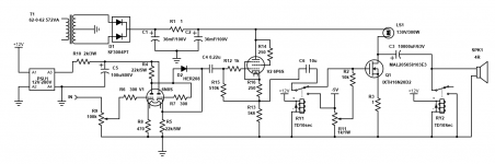
Since I know more about tubes than transistors, I've drawn up the amp with an added tube buffer.
By using a chassis mount DPDT relay I can free up the two corner octal sockets.
6P6S is overkill but I don't have 6BX7... no more room in the chassis to mount 9 pin sockets.
The crap I need will be here later. I'll report back then.
Attachments
Last edited:
The IXTH16N20D2 is a depletion mode (or rather a mixed mode), not insulated gate device, officially called "normally on silicon carbide JFET".
Not a JFET, if you ask me.
Not a JFET, if you ask me.
The datasheet calls it "Depletion Mode MOSFET"... Where are you finding it listed as a SiC JFET?
Rig it up in a circuit with a light bulb. If it's a real depletion mode part, typing gate to source will turn it on. if it's enhancement it would be off, no?
The IXTH16N20D2 is not a fashionable silicon carbide JFET (like the UJ3N065080K3S / UJ3N120035K3S), it does not have a gate-channel diode, but a terrible capacitive gate (5500pF) and a horrible reverse transfer capacitance (607pF) indicating a large current carrying capacity and small bandwidth.
Please accept my apologies.
Please accept my apologies.
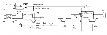
Ah I understand you now. Yes, it might not be ideal, but it's what I have to play with, and what I need to do is improve it by driving it with more current. I might even just redo the tube section - scrap the DC coupling and run the second triode harder. The 6SN7 is good fro 20mA and right now it's set at 6mA...
Another change I made is terminating the first relay at -5V instead of ground.
Another change I made is terminating the first relay at -5V instead of ground.
Attachments
Last edited:
Ok. So I increased the current to 12mA on the cathode follower. I think that will help overcome the 5500pF input capacitance... This way I get to skip the 6P6S tube. I also increased the B+ for the tube stage to 400V.
The more I muck with this design, the more I wish I'd used a 6F12P.
The more I muck with this design, the more I wish I'd used a 6F12P.
Attachments
Last edited:
- Home
- Amplifiers
- Solid State
- Any help? First attempt at a "hybrid" using depletion MOSFETS