so each channel has about 135w in each bulb and 65w into each mosfet?
( about 2.5A bias current)
( about 2.5A bias current)
EDIT: Yes I think if we're talking the 500W bulbs as load... It was too hot and without much to gain power wise.
Bias current is 1.6A per channel. Each MOSFET has 1.6A @ 27V, the bulb has 1.6A @ 50V. (with 300W bulbs)
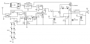
Here's another schematic with the added capacitors on the bias controls for stability. The relay positions are shown in the "ON" state.
Bias current is 1.6A per channel. Each MOSFET has 1.6A @ 27V, the bulb has 1.6A @ 50V. (with 300W bulbs)
Here's another schematic with the added capacitors on the bias controls for stability. The relay positions are shown in the "ON" state.
Attachments
Last edited:
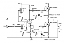
Depletion mode AB outout
Sorry about the haziness... http://www.denisvilfort.com/Depletion_Mode_Output.png
The resistors are 0.25 ohm - 5W.
D.
Sorry about the haziness... http://www.denisvilfort.com/Depletion_Mode_Output.png
The resistors are 0.25 ohm - 5W.
D.
you may want to place a 47 to 150 ohm resistor between the switching supply and C7 to filter out any high frequency hash from the power supply as the 6V6 or any tube has poor B+ noise rejection.
You should hear the noise without C7 at all 🙂 C7 seems to quench the noise though, but you're right. It would be generally a good idea especially since the current draw is pretty low, there's just not a lot of places to put one. The 6V6 is only running with around 20mA of plate current.
Really? A part that safely controls what, up to 16 amps? My goodness ..from #79 said:I'm thinking of designing something using these MOSFETs in source follower with transformer output.
The other notion concerns the Cathodyne phase splitter driving big FET's; maybe I'm too late to chip in my two bits -- it was back in post #11 (below, for convenience):
Since the upper (sourcing) part is providing only current gain, with no voltage gain; and the lower (sinking) device delivers both current AND voltage gain, shouldn't the cathode resistor value be approx ( plate_resistor / gFS ) - and gFS is about 5 at this 2-1/2A operating point?
That might even increase the end-to-end voltage gain enough to omit the input buffer/gain stage!
Oh, and -- keep an eye on your gate zeners. Maybe stick to Mark T's plan, 2 back to back 12V zeners will clamp to ~13V; the ones in this schematic are backwards and won't allow the IXYS MOSsies to turn off (negative Vgs) more than about 1 volt.
Love your signoff, by the way ..😉
Cheers
Attachments
Last edited:
The schematic in #82 is what I've built now 🙂 Single ended source follower. I blew up the left channel MOSFET last night (they REALLY don't like transients!) Do I need gate resistors to limit current like in BJTs? The 12V anti-series zeners were in the circuit but the MOSFET is now a wire.
Do I need gate resistors to limit current like in BJTs?
Yes, MosFets need gate stoppers to suppress oscillation.
This is different with BJTs, where the main purpose of the base resistor is to convert the drive voltage to a drive current (Fets are voltage-controled devices like tubes, whereas BJTs are current control).
I see... So not to limit gate current? I'm just trying to figure out why the MOSFETs occasionally turn into wires. They don't oscillate.
The combination of the gate resistor and the internal capacitances of the mosfet forms a low-pass filter that blocks high-frequency oscillation. Same as with the grid resistor used with tubes.I see... So not to limit gate current? I'm just trying to figure out why the MOSFETs occasionally turn into wires. They don't oscillate.
How do you know its not oscillating? If the oscillation is at very high frequencies you'll need a good scope to see it. Also, touching the mosfet pins with the scope probe sometimes changes the oscillation.
I've never seen a source/cathode follower oscillate... I understand about the oscillations and I use grid stoppers all the time (except on cathode followers). What I'm asking about is the gate current. If it possible that the gate is taking excess current and burning out or is that just a thing with BJTs?
Gate current is virtually zero with mosfets under normal operation. As I wrote before, mosfets are controlled by the gate VOLTAGE, not by current. Like tubes and unlike BJTs.
I understand that. Not talking about CONTROL. I'm talking about a situation where there is a transient voltage larger than the allowed Vgs (what if you yank the tube out? ~125V peak through the cap). Even though there are zeners to clamp the voltage to ~13V, there's a good chance the MOSFET will die. This is what I need to figure out. The amp sounds good, but if it goes wrong, it costs 9$ each time.
Last edited:
Being Depletion Mode parts, aren't they susceptible to loss of negative bias? The 1 ohm Source resistor isn't going to offer much protection if the part 'makes up its mind' to conduct everything the main rail cap can deliver.
The Gate-stopper resistors may be just the prescription for your iterative $9 pain. An oscillation could come and go in microseconds, having been *triggered* by a particular combination of momentary signal voltage and load phase angle. Unless you happen to have a storage 'scope watching it at the instant of its death, there might be no outward indication other than the click/thump and the fuse pop.
Cheers
Well it's been caused by HV transients from proceeding stages (tube preamp etc) that I never gave a second thought to before -- they are usually connected to other tube stages that won't die if you hit the grid with 120V for a moment.
Alright so I've seemingly fixed this issue by using a shorting relay while te tube warms up.
When the tube was a cathode follower, the voltage started a 0V and ramped up to 1/2 B+ slowly as the tube warmed up. As a grounded cathode amp, the output voltage spikes from 0V to B+ in an instant which is too much for the zeners to stop.
I'm using 6P3S now, as well. The 6V6 were worn out, and they cost too much to bother replacing it with the same or even 6P6S which cost more than 6P3S - go figure.
I also dropped one of the (*)*&#%$# light bulbs! Last two... They aren't sold here anymore... A 200W 22R resistor just wouldn't be the same so now looking for ideas... the original 130V 300W lamps are available, but they cur the current down. Maybe a 40W in parallel with it 🙂
Question: What about replacing the 12V anti-series zeners with this TVS?
SA7.0CA-E3/54
Should I go by clamping voltage or reverse voltage?
SA7.0CA-E3/54
Should I go by clamping voltage or reverse voltage?
Last edited:
- Home
- Amplifiers
- Solid State
- Any help? First attempt at a "hybrid" using depletion MOSFETS