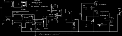
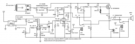
Here is the final current schematic that works properly... Ohms law says it's good for 10W at 4R and 20W at 8R... This is maximum power, it won't sound great at those levels... Still it is very enjoyable to listen to.
Attachments
Last edited:
So it sounds good -- that's great!
Can't quite put my finger on it, but there's something about having the bias pot, R11, span the output signal. Maybe that the low-frequency roll-off will vary with the bias setting; the amount of distortion and its distribution probably will as well.
It would add a bit more complexity (but you've already added a lot to the De-Lite😉), maybe bias the CCW end of R11 with a CCS and zener. Then if you fit the CW end to the output, instead of the Source terminal, should both improve stability and further reduce distortion.
Anybody run a sim on this yet? If not, I might give it a shot, but it'll take me a while.
Regards
Yes, you're right... This must be why Nelson Pass suggested I tie R11 from ground to B+ instead of ground to source. Still, C8 should stabilise the gate voltage, no? If I terminate R11 into B+, I'll need to pad the R11 to make adjustment easier - it's already a 5 turn pot but the smallest change on it makes already a 0.2V difference across the MOSFET.
I've never run a sim on the circuit (or any other circuit) but if you'd like to do it, That'd be cool... FWIW I'm now using 6P3S instead of 6V6 because one of them was bitched. Not sure how much that matters in a sim...
I also decided to try 400W as load: Current is now 2A instead of 1.6A. It seems to be a happy. I will post an update when I change the termination of R11. I might jump out R16 to see if the added voltage in the circuit would be better than the local NFB that it provides.
Attachments
Last edited:
if you are going to use a SS output, why not use a bridged amplifier with each side driven from the concertina tube. A car amp chip will deliver 25w from 15v.
this is the basis of a tubed car amp I am working on now.
this is the basis of a tubed car amp I am working on now.
Was going for a descrete design using DEP MOSFETs... The next design might involve IRFP240 and 9240, MJE340/350 for the front section... I still have not a lot of experience with SS stuff... I can build a wicked tube amp though 😛
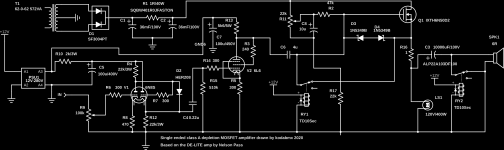
Ok... I modified it and the bias is definitely much more stable now!
Here's the updated schematic...
The bias now makes more sense, yes?
Here's the updated schematic...
The bias now makes more sense, yes?
Attachments
Last edited:
Umm .. now you have Vgs=0 'til the relay goes off -- near maximum conduction! Maybe not such a big problem with the load being LS1 ..
Also, C8's negative terminal should probably go to ground. That would provide better PSRR, and would attenuate the noise generated by the ~2 mA through the divider's resistors.
Anybody have an LTSpice model for the IXTH6N50?
Regards
Also, C8's negative terminal should probably go to ground. That would provide better PSRR, and would attenuate the noise generated by the ~2 mA through the divider's resistors.
Anybody have an LTSpice model for the IXTH6N50?
Regards
I always had Vgs=0V until the relay turned off 🙂 Indeed, because the load is LS1 switching the transistor "ON" just turns on the bulb and prevents Vgsmax being exceeded 🙂
Good point about C8. Although I don't hear any hum, I have two window shakers going in here, too.
Winter will be the true test. I built an amp for my dad's birthday which sounded fine here but I hear a hum at his place because the room is quieter. I'll add a choke to the front end to get rid of it in his case.
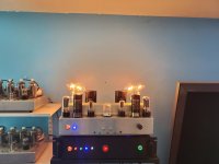
Ok. So after a day of listening I can't believe this thing is single ended. The change in biasing arrangement make a huge difference to the dynamics - It doesn't fall over on bass heavy tunes anymore and I find myself not needing to have it "full blast" to get anything out of it.
The heatsink is hotter than the 6N8S tubes, and about the same température as the 6P3S.. ~80C or so.
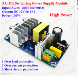
You could probably boil water on the 12V SMPS but it was 8 dollars and if it blows up nothing happens except the amp turns off so I'll keep cooking it and see how long it lasts. "Over temperature" if it has it hasn't kick in at least... The 12V SMPS is one of these. - I see the price went up.
AC-DC 110V 220V 230V to 12V 6-8A 100W Converter Switching Power Supply Module | eBay
The heatsink is hotter than the 6N8S tubes, and about the same température as the 6P3S.. ~80C or so.
You could probably boil water on the 12V SMPS but it was 8 dollars and if it blows up nothing happens except the amp turns off so I'll keep cooking it and see how long it lasts. "Over temperature" if it has it hasn't kick in at least... The 12V SMPS is one of these. - I see the price went up.
AC-DC 110V 220V 230V to 12V 6-8A 100W Converter Switching Power Supply Module | eBay
i use my el cheapo smps bricks sparingly wrt current specs, for example, smps 24 volts 6 ampere specs are loaded just 3 amperes, i never had any failure that way...i have repaired lots and lots of atx psu's many years ago....the key is never to abuse the and do not believe what the manufacturers tell you those can handle...
Attachments
Ok so as a test, I cranked the volume on the preamp to 10's of volts of clipping. Even with 12V anti series zener diodes between gate and source, the MOSFETS both f*cked off. They are basically wires now. I thought the zeners would protect from this? What am I doing wrong?
Wow .. super bummer .. I dunno. This could take some serious analysis.
I also have no idea how Depletion Mode MOSFETs feel about Gate stopper resistors. Could it need one?
Since the B+ for the preceeding stage is much higher, maybe a Schottky or something else fast, Cathode-Drain to Anode-Gate would help.
Just my 2 cents ..
edit: Just curious, what was going on in the (presumably) music at the time?
Last edited:
Nothing special - just nasty clipping. Of course my tube amps don't care at all when I do that sort of test LOL
I'm thinking of replacing the zeners with a bidirectional TVS.Maybe that will sort it. I'll do some voltage tests of power out vs input and see if I can clamp the input signal to the tube stage instead of relying on the protection diodes at the MOSFET.
I'm thinking of replacing the zeners with a bidirectional TVS.Maybe that will sort it. I'll do some voltage tests of power out vs input and see if I can clamp the input signal to the tube stage instead of relying on the protection diodes at the MOSFET.
Ok... A/C season is done and now I hear the hum. It's such a minuscule hum that most of you would tell me to live with it.
However, Since I designed it, and I have read Broskies site many time, I came up with a cross between Aikido and Janus...
C9, C10 and R19 make a hum injection scheme ala Janus. This should null the hum by injecting anti-hum, no?
Thoughts?
However, Since I designed it, and I have read Broskies site many time, I came up with a cross between Aikido and Janus...
C9, C10 and R19 make a hum injection scheme ala Janus. This should null the hum by injecting anti-hum, no?
Thoughts?
Attachments
Last edited:
No. They are still within spec or close enough to it.
TBH, I've never lifted a heater with DC. The closest I ever did was float it with DC. I routinely run 125-160V heater-cathode voltage with 6N1, 6N2, 6N3 etc and of course 6N8S/6N9S. I know it's not strictly "best practice" but I've never had an issue and it's way simpler since my 12V DC heater supply usually powers other things - Lifting it to 100V would also put 100V on control circuits and boost modules etc.
Question RE heater elevation though.
Say I wanted to make a push pull cathode follower XFMR coupled amp. Would I need to elevate all the output tubes separately? Or could i use a single supply for all the output tubes?
Last edited:
- Home
- Amplifiers
- Solid State
- Any help? First attempt at a "hybrid" using depletion MOSFETS