Well... SOON the end of The April Fool Day....
Here we had some leads :
- TDA1541 is good enough, many of us has already one (it keeps all his mojo in relation to the close TDA154x littles brothers)
- List about a futur group buy for negociate the price of a branded device has no sucess (zero answer)... it's a sort of DIY but maybe not funny enough or too much naive !)
- Jitter is important : few ways : Master clock (hard if a design for eveybody) FIFO partiel or not, Simultaneous Mode, USB async but no spidf, SDcard à la John (ECDesigns).
- An idea of the cost (Ceglar's input) : ECdesign player is the closest in term of price between the containder of ancient DIY world : John, Pedja, T. Loesch, (the less to the most expensive no regarding the final SQ... more or less close ?!)
- some proposition of experienced fellows : like the Gomez buffer for the last of its.
- some free partial shematics like the OP861 I/V from Pedja old (but good enough for something better that the Kits of todays and below the best branded), else : ready made FGPA à la RasberryPi ?
Is there a possible consensus around the "big" need of such a design : inputs (one, two ? USB, Disc, SD card + soft for data librairy), I/V, outputs, type of clock. PCB architecture : 4 layers or a double layer with a little of 3D for the core board ?
Give up ? Difficulty of working in 3 ways at the same time : technic, cost, time ?
That is just one of the potential beauties of it, use what you want - your personal (respected) view points
Not just a view point, rather a philosophy. Since the jitter is a great issue for any DACs, again, better thinking to a system. Ian Fifo buffer could be a starting point to approach a very low jitter level solution, with a very good clock close to the dac, sending back it to the source, fifo buffer in this case. Then you are free to feed the fifo buffer with what source you want, since it is isolated from the dac by the buffer.
Ask Thorsten, he thought always to a system, regardless to the dac chip.
Is there in a design the possibility to trace an output line from the MasterClock near the dac chip with an UFL conector at the end for slaving a source if wanted ? A buffer just before the UFL connector ? The rest of I2S maid by FIFO design à la Iancanada : multiple daughter boards ?
Polk for the source ?
1- SPIDF via FIFO
1 bis : I2S via FIFO for longer line ?
2- Embeded Async USB near the DAC chip ? (daughter board or not ?)
3- Disc ?
4- Something else ? (network datalibrairy via squeezebox clone and GLP like RasberryPi ?)
One or two of the items above ?
Whoa, whoa ... 😱
Vanofmonks has something that may be good-to-go, someone just needs to test it and then we can tweak ... 😕


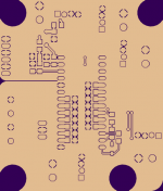
One thing that's critical is not breaking the ground plane with the outputs. Vanofmonks can you remove the output traces? Instead we could just use wires to go from the output pins as well as two ground wires coming from the ground pin to the output header. Or solder pin headers to the output pins and ground pin and copy the spacing/position on your output board and plug it straight in [3-d]) 😀


We could be 80% there already ... 😉
From:
OSH Park ~ dac1-v14
Vanofmonks has something that may be good-to-go, someone just needs to test it and then we can tweak ... 😕
One thing that's critical is not breaking the ground plane with the outputs. Vanofmonks can you remove the output traces? Instead we could just use wires to go from the output pins as well as two ground wires coming from the ground pin to the output header. Or solder pin headers to the output pins and ground pin and copy the spacing/position on your output board and plug it straight in [3-d]) 😀
We could be 80% there already ... 😉
From:
OSH Park ~ dac1-v14
Last edited:

Vanofmonks v8 sch and v10 PCB:


I sent Thorsten v8 sch/v10 PCB of Vanofmonks a while ago hoping it would get 'T approved' but ...
He said:
I have seen worse. Better too.
And when prodded a bit more:
There are a number of mistakes or sub-ideal choices in the actual schematic, more in the PCB Layout.
The connectors are wrong, no re-clocking on board. I cannot see the point. Pretty much 90% of what i suggested is being ignored.
But when asked for particular suggestions he didn't give any response (understandably, he's a busy guy and has given his hints).
Vanofmonks, what changes have you made since v8 sch and v10 PCB?
Well, it's a place to start ... 😱
Again, here are T's hints:
http://www.diyaudio.com/forums/digi...any-good-tda1541a-dac-kit-36.html#post2887893
Can someone with a bit of time make a summary and we'll get started!


View attachment tda 1541A.pdf
I sent Thorsten v8 sch/v10 PCB of Vanofmonks a while ago hoping it would get 'T approved' but ...
He said:
I have seen worse. Better too.
And when prodded a bit more:
There are a number of mistakes or sub-ideal choices in the actual schematic, more in the PCB Layout.
The connectors are wrong, no re-clocking on board. I cannot see the point. Pretty much 90% of what i suggested is being ignored.
But when asked for particular suggestions he didn't give any response (understandably, he's a busy guy and has given his hints).
Vanofmonks, what changes have you made since v8 sch and v10 PCB?
Well, it's a place to start ... 😱
Again, here are T's hints:
http://www.diyaudio.com/forums/digi...any-good-tda1541a-dac-kit-36.html#post2887893
Can someone with a bit of time make a summary and we'll get started!
View attachment tda 1541A.pdf
Last edited:
As a quick reply, I left the reclocker off the board because I figured between Ian's FIFO and the amanaro reclocker options from acko that it was covered. There does not look to be a big difference between the two versions, but one difference is I changed the smd components to have a silkscreen line showing orientation. Also looks like I changed the ground plane.
Sent from my iPhone using Tapatalk
Sent from my iPhone using Tapatalk
Maybe Studiostevus can help us as he tried already a credit card format with some of the hints of ECDesigns ? I'm sure specialist of RF will add some comments if the design is shared....beautifull discusions about PCBs and RF on the "I2S cable" thread ! (2 to 4 layers as a hifi standard but no free tools for drawing such pcbs for the enthusiasts !)
Vanofonk, nice compact design you are able to do !
I remember a guy here OSHifi fellow or something like that who play without the découplings caps but the two bigger first with 1 to 2 uF.*
For the LDOregs you have also some ultra low noise nice Micrel 205 (SOT 25) or Texas Instrument (SOT 25) this time without the need of near tantalum for the oscilations. You save space with it : TI LP5907 Ultra-Low Noise LDO Regulator | Mouser : just 2 X7R caps! no need of a specific shunt caps to gnd for low noise like the Micrel, but the Micrel is "less" noisy" !
i have got the good little Subbu DAC from what I learn how small is beautifull !
I found these 2.5 mm pads spacing polymer cap for the main 5V;-5V; -15V could work very well : 100 uf LF serie United Chemicon (ASAxxxx réf : Mouser). Maybe a 470 SEPC 16 V for the famous negative -15V but here spacings between leads is 5 mm.
SMD 100 uH coil just before the ldo regs or near the PS inputs connectors for PS boards ?
Is there a 4 pads something for a smd crystal near the TDA 1541 (if MCLK used to slave something ?) : some goods crystal at FOX... I just rewrite gentle advises here because not a specialist... Maybe enough space to putt beneath the board with cnd directly on the contigous Gnd and the clock line to the clock pad of the TDA1541 ?
Do you use the silmutaneous mode à la Pedja for the I2S input ?
For the I/V and buffer stage : is a stacked pcb design with an another board with short vertical connection to the core board a good idea for enthusiasts like us (idea of a 3D design by T. Loesch to make short when just two layers pcbs with contigous ground plane) ?
Just 2 cents, i know it's easier to write than draw !
Last edited:
Is there a guy more involved in technics who can gently drive... or eanyone for good technicals inputs about the free shared threads of VAnofonks and eslse above ?
Maybe time (if you people are interrested) to share short ideas about the architecture of the main board like Vano gently maid... please folks, did you believe than the "good planes" are maid by standalone people ?
Oh sorry the Ground-plane i mean ! (it's a joke !)
Maybe time (if you people are interrested) to share short ideas about the architecture of the main board like Vano gently maid... please folks, did you believe than the "good planes" are maid by standalone people ?
Oh sorry the Ground-plane i mean ! (it's a joke !)
For the damned - 15V : maybe one of the less noisy avaliable smd chip here (but expensive but already soldered: 20 USD) at ackoDAC :
Power Supply Products
NEW RELEASE
AKR47VH Super Regulator
e.g. Assembly
-High Speed, Ultra-Low Noise, 3-Terminal LDO Regulator
-Any output from 1.4V to 30V - resistor adjustable (R2, on-board)
-up to 1A output with 0.3V dropout
-5uV rms noise, typical
-Unique ground plane heatsink
-Supplied as boards with IC mounted only. Add the rest and enjoy the build!
-Vertical or horizontal mounting, standard 3-Term 78xx pinouts
-30mm x 20mm
-Schematic, BOM and support information provided
Don't know if a negative one is possible ?
Spinning!
No offense Eldam but reading your posts could be an endurance. Your style of writing makes me dizzy. You an energetic member, hope to see more of you.
Maybe Studiostevus can help us as he tried already a credit card format with some of the hints of ECDesigns ?....................................................................................................................................................................................................................................Just 2 cents, i know it's easier to write than draw !
No offense Eldam but reading your posts could be an endurance. Your style of writing makes me
dizzy. You an energetic member, hope to see more of you.Yeap new2 hifi...sorry, that s why i can not be a driveR of such project here.
Studiostevus maid a motherboard which has the size of a bank card.
I m not the man but hope some will share little by little. As we have all different level of knowledge, a simple rule could be : basic people like me try to do what they can (as to be more discret) knowledged fellows answer or rule thread by thread like in the other posts Expert stop us from taking a bad direction or give a little help. Maybe nothing will happen... maybe not. each people can put a stone to make a bridge ! The best of us should give a little of their sucess and not keep it too much : we just want a middle way, not the worst and not the better because of the task and the final price ! The more expensive is the experience and knowledge : please folks : give just a little part to us please...
Last edited:
Vanofonk,
If a little money is needed to print several pcbs : one or two at each step : we can maybe share fees by a service GB with PayPall : payement as a service !
I'm not a rich man in this moment but each stingy can give few bucks. 1 dollars cost you 1.04 dollars with the PP fees . Here in France we prefer gang bangs than onasism . We are not sharing Scarlett Johansson... "Oh sorry Darling... go back to sleep"... yes she likes the frenchs*)
Levarage Buying Out is your friend (is it said like that in english ?)
* : english litterature is only here to give a rythm ! Like Steevie Wonder ...
If a little money is needed to print several pcbs : one or two at each step : we can maybe share fees by a service GB with PayPall : payement as a service !
I'm not a rich man in this moment but each stingy can give few bucks. 1 dollars cost you 1.04 dollars with the PP fees
. Here in France we prefer gang bangs than onasism . We are not sharing Scarlett Johansson... "Oh sorry Darling... go back to sleep"... yes she likes the frenchs*)Levarage Buying Out is your friend (is it said like that in english ?)
* : english litterature is only here to give a rythm ! Like Steevie Wonder ...
Yeap new2 hifi...sorry, that s why i can not be a driveR of such project here.
Studiostevus maid a motherboard which has the size of a bank card.
...
I said eurocard, not bank card. That's about 4x a bank card.
Yes I offer to share, but under the condition that some knowledgeable people improve what my novice skills could not do, so get to learn something here as well. Have not seen a confirmation of that yet.
Both design and layout are surely not optimal. Far from AMR that's for sure.
Btw, I used to have Oliver's first board, and my design is likely better that that, but looking at his latest Red Baron, I think they are quite close (mine having the power section on the board)... Why don't you guys use that?
Btw, I used to have Oliver's first board, and my design is likely better that that, but looking at his latest Red Baron, I think they are quite close (mine having the power section on the board)... Why don't you guys use that?
I kind of agree - Its probably better than a ground up build based on archived thoughts.
Still think that if you had enough people to approach Pedja to buy his discontinued AYA II DAC board you'd be (miles) in front. Of course you'd need to approach it with the right intentions (the guy has been burnt by people copying his designs and then going commercial, before) and you'd likely only get one chance with the approach, so perhaps if you were to decide to try, make it count, ask with conditions like min 100pcs, NO commercial use.. I'm still big on the charity donation thing. Whats the difference if it costs you $100 instead of $40?.. you'll soon see how much time it takes to build such a thing properly and then $60 to have the better design in the bag, is no big deal.
Get the gerber, use the PS which is onboard (the common mode RC filtering and discrete shunts with final filters right at the 1541A pins) and 1541A section, delete the 2mA offset on the output, modify the input section for jumpable I2S or PCM input, bring the outputs out directly from the chip so that you can use what you like and be done with it - get them printed up, size would be approx 120mm x180mm.
Feed it with anything from simple WaveIO via I2S (or similar) through to full Ian FIFO set up via PCM (simultaneous)
Anyway..
Ooops forgot to ask; Studiostevus - I'd be interested to have a look at your output stage, Gomes is uncommon to me although I understand its similar to Broskie's Aikido Circuit
Last edited:
Both design and layout are surely not optimal. Far from AMR that's for sure.
Btw, I used to have Oliver's first board, and my design is likely better that that, but looking at his latest Red Baron, I think they are quite close (mine having the power section on the board)... Why don't you guys use that?
Thank you Studiostevus to answer,
Yes the RedBAron has the merit to exist and the effort to develop it are constant. The price of it is not delirious either and it's far better than some Chinese kits. But some issues of design were pointed in some threads above than Vanofonk improve :
- more compact
- decoupling are nearer to the dac chip
- supplying and regs (which is crucial) are close with low noise regulation
And not sure than the output stage of RedBaron deserve a fly !
I kind of agree - Its probably better than a ground up build based on archived thoughts.
Still think that if you had enough people to approach Pedja to buy his discontinued AYA II DAC board you'd be (miles) in front. Of course you'd need to approach it with the right intentions (the guy has been burnt by people copying his designs and then going commercial, before) and you'd likely only get one chance with the approach, so perhaps if you were to decide to try, make it count, ask with conditions like min 100pcs, NO commercial use.. I'm still big on the charity donation thing. Whats the difference if it costs you $100 instead of $40?.. you'll soon see how much time it takes to build such a thing properly and then $60 to have the better design in the bag, is no big deal.
Get the gerber, use the PS which is onboard (the common mode RC filtering and discrete shunts with final filters right at the 1541A pins) and 1541A section, delete the 2mA offset on the output, modify the input section for jumpable I2S or PCM input, bring the outputs out directly from the chip so that you can use what you like and be done with it - get them printed up, size would be approx 120mm x180mm.
Feed it with anything from simple WaveIO via I2S (or similar) through to full Ian FIFO set up via PCM (simultaneous)
Anyway..
Ooops forgot to ask; Studiostevus - I'd be interested to have a look at your output stage, Gomes is uncommon to me although I understand its similar to Broskie's Aikido Circuit
Hi Ceglar,
There are jlawer men for that, we can fill in a form : I'm the first here to write than it needs maybe guaranties (look above what I wrote).
You have always the risk when someone buy something to have reverse engeneereing !
And why not buying the last than the old one ? Advantage of GB is to give enough money for the seller to reduce its costs : win win. Not to have the old at the price at the old ! Maybe I'm naive !
But I try to be always positive with ideas if i can : I read your post as an idea than brands could sell their "not last design" at a lower price with group buy they manage themselves (idea ?!). But maybe hidden grupBuy could work too with guarenties for the brandnews products ! People do it for cars, basketts and so on ! Times are hard todays !
DIY is good but still thinking we are all gonna diy and having a reference to listen then compare to iys own diy is the best idea than a lover of music and hifi can have. The OP here didn't mistake with buying a good CD player. But here it's individual, I'm talking myself for people like me not having a reference player yet ! Forum are to share... design, hints... or GB... or whatever for a grup not just one.
I'm always thinking : share and you will see what happen.... maybe more surprises than doing nothing ! Its hard but getting older I try tyo do it the more I do...
my two cents
Last edited:
Houps forgett one thing : the post of Ceglar and StudioStevus about tubes :
Printed Circuit Boards and Kits : serious vendor for a daughter board about an TDA1541 output.
But I don't know if I/V need to be set up with such products. ref of tubes need discussions : Siemens 3A, 6922, etc....
Never try myself tubes because the price with branded products and the risk of death with high voltage at my level of skill with DIY ( I have never to work with wood yet !)
read again your post Ceglar, yes maybe having the AYA boards at 100 dollars is a good idea, but with my english (and you can not hear me when I'm talking english... it's worst) ... I can not manage it myself ! Is Pedja from your countrie ? A local fellow could maybe try... Australian are not big by the number but very active people with incredible results in regard to that... Good state of mind in your country...
Last edited:
Ooops forgot to ask; Studiostevus - I'd be interested to have a look at your output stage, Gomes is uncommon to me although I understand its similar to Broskie's Aikido Circuit
I don't have any drawings as it's built p2p, but have a look at broskie's page, it's on there as well somewhere. The key is that you don't eliminate the -2mA idle current, but you take advantage of it (no need for a resistor to create the tube's idle current, if I recall correctly). It's been a while since I've done that
- Status
- Not open for further replies.
- Home
- Source & Line
- Digital Line Level
- Any good TDA1541A DAC kit?