The motor has been for a long time in my drawer. I believe it's part of a washing machine. The gears are spare parts from a broken printer. It was tricky to combine them for a 2:1 reducer to allow the 48 steps motor to drive the 24 position switch since it has to substitute the "clicks" of the removed bearing ball lock mechanism. From a quick and dirty test seems to work smooth and accurately. Electronics for the motor will follow. Any suggestions are welcome.

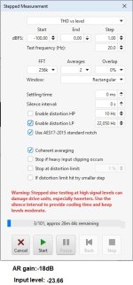
No.Great! Now everyone knows that I can hear up to 100kHz...👽
The sweeps were only up to 96kHz 🤣


Wired, at last! It is now I realize George's epic effort to build all these prototypes! A million thanks for his work and his help to build one for my system! Already tested and works fine. Steps between channels are absolutely symmetric. In balanced configuration, it seems to enhance CMRR too. Inserted in my soundcard's loopback, it lowers THD+N significantly. Despite the mess, I tried for right angle crossings and apparently it pays off. No undesirable effects. Time to look for a remote control.
Attachments
MagicBus,
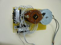
Would you post a picture of the other side? Did you use a belt/pulley system to drive the switch?
Would you post a picture of the other side? Did you use a belt/pulley system to drive the switch?
Hello,
I have been enjoying lurking on this thread, thank you for the posts!
I have a question about winding with regards to adding taps.
I am assuming the process is:
Is this correct? Do you try to keep the winding neat while doing this? I feel like it would be nearly impossible to keep it properly tensioned and positioned through this process.
Cheers
I have been enjoying lurking on this thread, thank you for the posts!
I have a question about winding with regards to adding taps.
I am assuming the process is:
- wind the wire
- at a set number of rotations to make a tap you stop winding
- solder the wire to whatever output you're using for said volume level
- try to start winding with the wire close to where it was when you stopped for this tap
- repeat
Is this correct? Do you try to keep the winding neat while doing this? I feel like it would be nearly impossible to keep it properly tensioned and positioned through this process.
Cheers
Kostas thanks!
Excellent work with the wire spaghetti.
Arrange for the dressing, the accompanying wine and bon appetite
Hi cibo
On my rudimental winding jig, tensioning and wire feeding are done by my fingers.
Tensioning is OK but wire turns are not neatly placed side by side
How I do it is:
Wind the wire
Two-three turns before reaching a set number of turns, I progressively bring the wire close to the side where the target tap is located, I complete the target number of turns and I stop winding
I turn the wire two-three times around the tap pin. (I solder the wire on all the pins at the end).
I then continue winding, starting one-two turns at the side close to above tap. Then I progressively guide the wire close to where I had moved away from the previous winding and I move on turning.
Repeat
🙂
George
George, it sings!!! 🙂 Thanks so much for the idea and all the work you do.... It seems very very promising, sound even in lab is great!
Soon it will be on the big system for review

Soon it will be on the big system for review
You are welcome Theodor.
I see a lot of switching relays, heatsinks, power transistors.
A lot of goodies and a lot of boards!
Remote control of AVC via relays? 😉
George
I see a lot of switching relays, heatsinks, power transistors.
A lot of goodies and a lot of boards!
Remote control of AVC via relays? 😉
George
Everything for AVC, I use MUXes to control relays. I control MUX with Raspi zero (and everything else). I also use IR for remote control.Big stuff! Is it all this only logic for the AVC or does it include any analog buffers?
Gpapag yes relays to coontrol the AVC. Some of the relays are input and output control
Guys sound in lab is excellent!
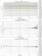
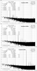
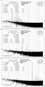
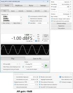
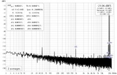
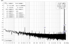
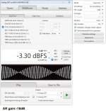
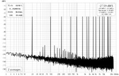
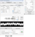
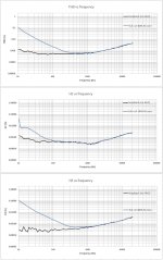
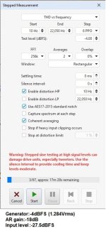
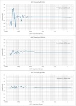
Just an update for your amusement! Although the first prototype mechanically was fine, I wasn't able to pair it with suitable electronics. There are a few stepper motor drivers available but they are not designed with volume control in mind. They did work but I had to chase the rotation with an awkward combination of buttons that made it non practical. Let alone the garage door remote control... So, I moved to another module that is designed for this job and it's great!Wired, at last! It is now I realize George's epic effort to build all these prototypes! A million thanks for his work and his help to build one for my system! Already tested and works fine. Steps between channels are absolutely symmetric. In balanced configuration, it seems to enhance CMRR too. Inserted in my soundcard's loopback, it lowers THD+N significantly. Despite the mess, I tried for right angle crossings and apparently it pays off. No undesirable effects. Time to look for a remote control.
Meanwhile, I thought to tide up the spaghetti wiring...
Looking forward to install it in my preamp.
- Home
- Source & Line
- Analog Line Level
- Any chance for a diy autoformer volume control?