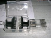
The PCB mounting of the switches is great! You saved so much soldering. What rotary switch are you using ?
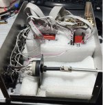
Amazing work. Wish I could listen to itJust an update for your amusement! Although the first prototype mechanically was fine, I wasn't able to pair it with suitable electronics. There are a few stepper motor drivers available but they are not designed with volume control in mind. They did work but I had to chase the rotation with an awkward combination of buttons that made it non practical. Let alone the garage door remote control... So, I moved to another module that is designed for this job and it's great! View attachment 1380762 But this is for two wires motors so, I had to rebuilt the mechanism. New gear train for the weaker motor and careful alignment, or it won't rotate.
View attachment 1380764View attachment 1380765
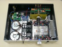
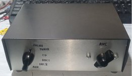
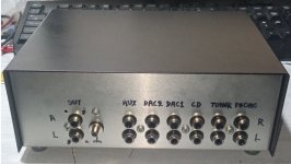
Meanwhile, I thought to tide up the spaghetti wiring...
View attachment 1380766View attachment 1380769View attachment 1380770
Looking forward to install it in my preamp.
It was a donation, similar to this: https://www.google.com/url?sa=t&sou...IQFnoECBkQAQ&usg=AOvVaw12vrXinyVLHJ_tadOGdnZ7The PCB mounting of the switches is great! You saved so much soldering. What rotary switch are you using ?
It won't take long to finish! 🙂Amazing work. Wish I could listen to it
Indeed. That is amazing work.Amazing work. Wish I could listen to it
Kostas is a master of solving problems in a unique way. And a great recycler of otherwise scrap components 👍
We can arrange for a meeting 😉
George

I notice one of the pins of each switch is bent up and doesn't solder to the PCB - wondering why. Using FR4 structurally is good - but did you miss a trick? If you used single-sided copper clad FR4 you could have grounded all the metal parts for free?Meanwhile, I thought to tide up the spaghetti wiring...
The bent pin is the "wiper", it was shaped like this and I didn't want to stress it anymore. It is soldered to the PCB superficially, and a wire will be attached on this.
I just had this clear FR4 piece reminding me a failed home etched PCB... I didn't thought about grounding. Using it in its temporarily manual version was fine. I haven't listened to this one yet. I'll report any findings.
I just had this clear FR4 piece reminding me a failed home etched PCB... I didn't thought about grounding. Using it in its temporarily manual version was fine. I haven't listened to this one yet. I'll report any findings.
Here you are! Did I mention careful alignment required? 

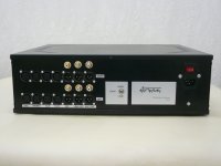
In full working order now. It doesn't seem to need grounding of the metal parts of the switch/shaft. Just very low level EMI picking, mostly dependent on the position and definitely inaudible. As already said, it's installed in front of a -doubled for pseudo-balanced i.e. one SE channel per phase- Salas DCG3, but also have provided for a passive output. So, in this configuration, this is DCG3 alone, no AVC.

This is AVC passive.

And this is AVC with DCG3

In full working order now. It doesn't seem to need grounding of the metal parts of the switch/shaft. Just very low level EMI picking, mostly dependent on the position and definitely inaudible. As already said, it's installed in front of a -doubled for pseudo-balanced i.e. one SE channel per phase- Salas DCG3, but also have provided for a passive output. So, in this configuration, this is DCG3 alone, no AVC.
This is AVC passive.
And this is AVC with DCG3

George kindly performed a complete set of measurements on my preamp! I'm posting just a few representatives, all in balanced mode.
AVC dual tone

AVC+DCG3 dual tone

Frequency response and phase

AVC multitone

AVC+DCG3 multitone

And THD at input level typical of my system's gain structure.

I'm posting just a few representatives, all in balanced mode.AVC dual tone
AVC+DCG3 dual tone
Frequency response and phase
AVC multitone
AVC+DCG3 multitone
And THD at input level typical of my system's gain structure.
I forgot to post the loopback measurements for reference, so here you are:
Dual tone balanced


Frequency response


Multitone balanced


And single tone balanced measurements:
First AVC

AVC+DCG3

And loopback


As already mentioned, these are all in balanced mode. George has also measured everything in SE mode and it shows just a bit inferior. OTOH, there is significant degradation when DCG3 gain switch from x2 shown here to x6.
Dual tone balanced
Frequency response
Multitone balanced
And single tone balanced measurements:
First AVC
AVC+DCG3
And loopback
As already mentioned, these are all in balanced mode. George has also measured everything in SE mode and it shows just a bit inferior. OTOH, there is significant degradation when DCG3 gain switch from x2 shown here to x6.
This is so cool, nice job!Just an update for your amusement! Although the first prototype mechanically was fine, I wasn't able to pair it with suitable electronics. There are a few stepper motor drivers available but they are not designed with volume control in mind. They did work but I had to chase the rotation with an awkward combination of buttons that made it non practical. Let alone the garage door remote control... So, I moved to another module that is designed for this job and it's great! View attachment 1380762 But this is for two wires motors so, I had to rebuilt the mechanism. New gear train for the weaker motor and careful alignment, or it won't rotate.
View attachment 1380764View attachment 1380765
Meanwhile, I thought to tide up the spaghetti wiring...
View attachment 1380766View attachment 1380769View attachment 1380770
Looking forward to install it in my preamp.
I wonder if you might share a few details about this? How did you go about sizing the gears to make it turn the rotary switch? I think you mentioned you removed the ball detent to use the stepper motor, does this still apply with this motor, and it looks like this is the motor that came from the remote control unit and you just removed the attenuator part?
Also, what happens when you get to the ends of the switch, do you just have to release the remote button as to avoid burning up the control motor?
I would really like to try to make one of these, any advice or tips would be great!
Thanks,
Sean
Thanks!
It is correct I removed the ball so that the switch rotates freely. Otherwise there is no reasonably sized motor to turn it. So, thinking that the steps should be tracked, I used the stepper motor as explained in posts #159 and #161. Then, in post #180 it is explained why I moved to the two wires motor. In the meantime, I was using the switch/AVC manually and I realized that it was not necessary to track the steps. Since the switch is "make before brake" it's not going to be open at any time. Worst case it will short circuit two taps but I didn't find this to cause any measurable or audible problems. So, I used a gear train that could work with the new motor's torque. Both the motor and the gears came from a broken printer, great source for parts like this! When reaching the end of the rotation the motor makes a noise similar to the stepper one, like repeated "clicks". It seems it can take it for a moment but of course, I don't insist for a long time. My interpretation is that the remote control module drives the motor with pulses rather than DC but I can't tell it for sure.
A few days ago I visited a local shop specialized to microrobotics. Lots of nice parts for a project like this. Although mine works flawlessly, I feel the itch... again.
Thanks for the explanation, that should get me started.
I'm going to order some random gears sets and see if I can cobble one together. Is there anything special on the gearing size ratios, or did you piece it together using the gears you had?
I'm going to order some random gears sets and see if I can cobble one together. Is there anything special on the gearing size ratios, or did you piece it together using the gears you had?
Just random parts. Even in the first version with the accurate 2:1 reducer, I put together what I had. In the second version, the gear train was extracted from the printer in one piece together with the metal base. Here is something not exactly relevant but very inspiring at least.
especially after 6:30.
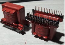
Another set (the 3rd) of 24 step AVC with 1535 turns of 0.2mm copper wire on EI35 80%Ni core has been wound and installed in a box.
Technical details are the same as in posts #160 to #170 🤓
Here, only photos 🙂
George
Technical details are the same as in posts #160 to #170 🤓
Here, only photos 🙂
George
Attachments

MagicBus has really skills in creating things!! 🙂
George, thank you so much for creating this AVC for me...
Preamp is now finished and sound now is out of this universe. Never heard again such a magnificent preamp. Beats absolutely everything ever heard
George, thank you so much for creating this AVC for me...
Preamp is now finished and sound now is out of this universe. Never heard again such a magnificent preamp. Beats absolutely everything ever heard
- Home
- Source & Line
- Analog Line Level
- Any chance for a diy autoformer volume control?