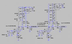
These are the circuits.
The recommended BJT has a tad higher THD but more important, it has LOWER 3rd and uneven harmonics.
.SUBCKT 6V6 P S G K
Esp 2 0 VALUE={V(P,K)+13.49*V(S,K)+130.4*V(G,K)}
E1 3 2 VALUE={5.521E-7*(PWR(V(2),1.5)+PWRS(V(2),1.5))/2}
E2 3 4 VALUE={5.521E-7*PWR(13.49*V(S,K),1.5)*V(P,K)/25}
E3 5 4 VALUE={(1-V(4,2)/ABS(V(4,2)+0.001))/2}
R1 5 0 1.0K
Gk S K VALUE={V(3,2)}
Gp P S VALUE={0.92*(V(3,4)*(1-V(5,4))+V(3,2)*V(5,4))}
Cgk G K 4.5P
Cgs G S 4.5P
Cgp G P 0.7P
Cpk P K 7.5P
.ENDS 6V6
Attachments
Thanks. Will check some semiconductor substitutions with that model too. What is the gain the circuits give?
Do a listening-test with the BJT vs the MOSFET-version. If going MOSFET I guess the 9610 will be OK. Instinctively I like the BJT best.....
Isn't 80v sufficient? How much voltage will be dropped across the transistor with a B+ of 280v?
Would a darlington give better performance in the lower position?
Would a darlington give better performance in the lower position?
We normally shoot for half B+ on anode. So in your example is (140V - LEDs drop) + VGS or Vbe. That is for Q2.
For using a Darlington, I don't know. But it may be more prone to oscillation in practice?
For using a Darlington, I don't know. But it may be more prone to oscillation in practice?
Is half B+ the best operating point? Or something higher?
You may not want to swing so low that G1 is conducting.
Where then is your most useful center?
You may not want to swing so low that G1 is conducting.
Where then is your most useful center?
kenpeter,
As you indicate Ua probably should be higher than 0,5xB+ to get symmetrical clipping. One will need to check the loadlines in the specific tubes UaIa-curves. The sand-package probably needs 10-20V.
As you indicate Ua probably should be higher than 0,5xB+ to get symmetrical clipping. One will need to check the loadlines in the specific tubes UaIa-curves. The sand-package probably needs 10-20V.
Roughly 10V for the upper, and roughly (B+/2)-10 for the lower, plus sink for it if enough current is running. That is the ballpark for choosing max V ratings of the semiconductor parts IMO.
SY said:
Longer tube life? Do you mean because of the inability of the bias voltage to adjust itself as the tube ages and starts getting gassier?
Yes, I mean that negative feedback on DC that we loose stabilizing an absolute value of a bias voltage.
I missed this thread before, sorry. Otherwise I would have commented on your very clever circuit. That's an interesting variation on a CCS. I use gyrators for active crossovers, but never have as a plate load. Excellent idea!
Thanks! It was a logical evolution of this servo (a first, I decided to load the tube on a CCS, and then decided to shorten the servo path so it's impact on the signal will be less audible):
As I mentioned earlier you must use the Ua/Ia-curves to decide workingpoint.
With 6V6-trioded, B+ 300V , Ia 20mA, load above 10k and the BJT/Mosfet version, we can swing between 65-70V and 290V. This means the workingpoint should be choosen at ca 180V. This is where you will get symmetric clipping and max output.
With 6V6-trioded, B+ 300V , Ia 20mA, load above 10k and the BJT/Mosfet version, we can swing between 65-70V and 290V. This means the workingpoint should be choosen at ca 180V. This is where you will get symmetric clipping and max output.
Mine has B+ 330V and anode was about 210V and Ia about 22mA. Came out practically near my chosen point on the curves.
For valves with a lot of voltage swing, such as your examples, I guess you would need to drop quite a bit of B+ across the transistors, but what about a preamp with only a few volts swing?
In post 55, Revintage quotes an equivalence to about a 60H choke. One of the great advantages of loading an anode with inductance is that it allows you to run off a lower B+ while still maintaining your voltage swing. Does this not also apply with this circuit?
In post 55, Revintage quotes an equivalence to about a 60H choke. One of the great advantages of loading an anode with inductance is that it allows you to run off a lower B+ while still maintaining your voltage swing. Does this not also apply with this circuit?
hihopes said:
In post 55, Revintage quotes an equivalence to about a 60H choke. One of the great advantages of loading an anode with inductance is that it allows you to run off a lower B+ while still maintaining your voltage swing. Does this not also apply with this circuit?
No, it is not a real coil that saves an energy in a magnetic field, it is an electronic simulation of a coil that spends an extra energy to work. But it dissipates much less of an energy than a plain resistor would do for the same results.
I have downloaded the datasheet for irf9610 from International Rectifier, but it doesn't show the pinout - just says it is a TO220AB package. As far as I can find out, this seems to have a pinout of G,D,S (looking from the front). Can anyone confirm this? I am drawing up a PCB and obviously need to get this right. I can post a jpg of the PCB if anyone is interested, or would like to give feedback on it.
- Status
- Not open for further replies.
- Home
- Amplifiers
- Tubes / Valves
- Anti-Triode SEPP, how to do best?