(continued from previous post)
So depending on the source impedance driving the circuit, sometimes the simple emitter follower is more linear, and sometimes the cascoded version is more linear.
Now we really haven't learned much new by this exercise. All we have done is look at how the load line (8 ohms) cuts across the characteristic curves of the device. And as I noted in a previous post, there isn't any magic about the cascode in this regard.
However we must explain the result shown in the white paper on your web site, and this isn't so hard to do. First of all, we note that the generator impedance used was 4.7 kohms. Second, we note that the test frequency was 15 kHz. So putting all of these facts together, it becomes fairly apparent that the mechanism for distortion reduction in your test was the fact that the cascode linearized the input capacitance of the emitter follower. This in turn allowed for lower distortion when fed from a higher impedance source.
Now a distortion reduction is a distortion reduction, and I'm not going to argue with that. But I think it is important to understand that the mechanism is not because "cascodes are more linear" as is commonly believed. Instead, the linearization of input capacitance *can* cause lower distortion from the driver circuit *if* it has a high output impedance.
Best regards,
Charles Hansen
Charles Hansen said:the linearization of input capacitance *can* cause lower distortion from the driver circuit *if* it has a high output impedance.
I really have to wonder about someone who quotes themselves.... 🙂
When I re-read what I had written, it reminded me that a big Japanese company made this claim in the mid-70s. It was about the time of the Yamaha B-1 and B-2 power amps. They had a brochure that showed a graph of the distortion reduction above 50 kHz when using a preamp with a high output impedance because the input diff pair was cascoded in the new model of amplifier.
We still don't quite agree. I'm sure that we will both nod our
heads when I note that the high source impedance throws the
effect into sharp relief, but we disagree that it is the capacitance
of the junction (this was a BJT, by the way). My observation
was that is was simply a current gain variation due to varying
voltage C-E and C-B. This is pointed out by the characteristic
shown in Fig 2 of the article, where the CE current is seen to
vary with voltage for a constant base current. By the way, the
circuit was operated as shown - there was no load. With a
load, the distortion was worse for both cases.
If I recall correctly, cascodes prefer a really high-Z load from the following stage. If so, then no-load translates into infinite-load, more or less.
With that in mind, the nature of the load of the following stage becomes of interest. Given that MOSFETs and JFETs have a much higher input impedance, would they not be preferred over bipolars? And even moreso if the following stage has devices in parallel, such as a typical output stage.
Grey
With that in mind, the nature of the load of the following stage becomes of interest. Given that MOSFETs and JFETs have a much higher input impedance, would they not be preferred over bipolars? And even moreso if the following stage has devices in parallel, such as a typical output stage.
Grey
I think all these devices have their place, and situations can
be constructed in which each shines. We are fortunate to
have such a variety to play with. 😎
be constructed in which each shines. We are fortunate to
have such a variety to play with. 😎
Hi all,
interesting notes about CC, how about a cascoded CE stage?
Jam,
you noted the sound getting "compressed", may I ask what kind of transistors you used for the input and cascode when you discovered said expression? Perhaps you could give also resistor values and CCT current for your setup?
Regards,
Michael
Charles Hansen said:Good question, Jan. I think the answer is actually the opposite. If you look at the characteristic curves of either a bipolar or FET, the curves are spaced further apart as the drive signal increases. (Exponential for bipolars and square law for FETs.) The Early effect (found to one degree or another in all solid state devices) compounds this problem, making the curves grow even further apart as the drive signal increases when there is high voltage across the device.
But if you draw a resistive load line over those characteristic curves, when there is high current there will always be low voltages across the device. So the impact of the Early effect is mitigated to a large degree when using a resistive load.
Disclaimer: The above is based solely on graphical analysis. I have not verified it with simulations nor actual tests on real circuits. So it may not even be true. 🙂
On the other hand, cascoding a device will tend to eliminate the (often non-linear) Miller capacitance. This *can* create a large benefit to the stage *prior* to the actual stage in question. So it is possible that while cascoding does not increase the linearity of the stage in question, the linearity of the overall design may be increased by cascoding.
Hi Charles,
The point I was trying to make is that with cascode, the voltage across the device can be made to be constant. If (for a bipolar; substitute suitable terms for FET or tube) the Vce remains constant during the signal cycle, there is NO early voltage effect; the Ic/Vce curve is a straight horizontal line, so linearity definitely is MUCH better than without the cascode. This is independent of the miller cap reduction (although it depends on the same effect, of course).
Jan Didden
Michael,
I was using MPSA8099 and MPSA8599. I have to admit the effect was slight. I did note that increasing the current through the differential seemed to reduce this effect. Now on the other hand cascoding the VAS hsd mixed results sometimes for the better sometimes for the worse and highly dependant on the type of devices used.
Mr.Pass has noted compression effects when cascoding the output stage and this is readily apparent if you try it. It would be great if we could identify the mechanism that causes this.
Regards,
Jam
P.S. For your information the differential was biased at 2mil. with 1.5k ohm collector resistors and no degeneration and 25volt rails with a current source attached to the tail of the differential.
janneman said:The point I was trying to make is that with cascode, the voltage across the device can be made to be constant. If (for a bipolar; substitute suitable terms for FET or tube) the Vce remains constant during the signal cycle, there is NO early voltage effect; the Ic/Vce curve is a straight horizontal line, so linearity definitely is MUCH better than without the cascode.
Hello Jan,
I disagree with your interpretation of what the cascode does. Your description is consistent with the graphs shown in NP's paper on the Pass website:
http://www.passlabs.com/pdf/cascode.pdf
In this paper he shows a cascode restricting operation to a very tall, skinny rectangular box (figure 5). In the next figure (6) he expands this box out to show that the lines are essentially horizontal, with essentially no Early effect.
However, there is a alternative way of looking at a cascode operation that is much more intuitive. Think of a cascode transistor (for the purposes of the present discussion) not as a common base amplifier, but instead as an emitter follower. This cascode transistor is now acting as the load for the input transistor. Now the output impedance of an emitter follower is simply 25 / Ibias(mA).
So let's look at a typical input stage, and compare a cascode with a non-cascode. The non-cascode input transistor would have a load that would typically be in the thousands of ohms (depending on the chosen resistor value). But when we put the cascode on, the input transistor now sees a load in the tens of ohms (depending on the bias current chosen). This much lower load has two effects:
1) It changes the slope of the load line drawn across the characteristic curves. The non-cascode will have a diagonal load line cutting across the curves, while the cascode's load line will be nearly vertical.
To make a graphical check of the linearity, we simply plot the distance between each intersection of the load line and each characteristic curve. The ideal amplifier would have perfectly equal spacing between each curve. In that case, the output current would be exactly proportional to the input signal and there would be no distortion.
I invite you to take a graph of a transistor's characteristic curves and plot a few load lines, both vertical (as for a cascode) and diagonal (as for a non-cascode). Very quickly you will see that there is no distinct advantage one way or the other with regards to linearity (uniformity of spacing between intersections).
2) The other thing that happens with a cascode is that the "emitter follower" load essentially "clamps" the collector of the input transistor at a fixed voltage. This means that there is very little voltage gain in the input stage. It is this lack of voltage gain the results in the lack of Miller effect.
Remember that the Miller effect multiplies the base-collector capacitance by the gain of the stage. But what is often overlooked is that the base-collector capacitance varies markedly with the emitter-collector voltage across the device; i.e., it is a non-linear capacitance. Cascoding reduces this non-linear capacitance in two ways. By minimizing the variation in emitter-collector voltage, the base-collector capacitance is stabilized. And then since there is no voltage gain in the input stage, there is no multiplication of the base-collector capacitance. When a high impedance source is combined with a non-linear input capacitance, there will be distortion at high frequencies. This is *not* due to the lack of linearity of the non-cascoded circuit per se, but rather to the interaction of the imperfect signal source and the non-linear input capacitance.
To summarize, I want to emphasize that I am *not* saying a cascode is bad, or that they should be avoided, or any such thing. It is a useful tool in our arsenal that has its place and should be used when appropriate. But I strongly disagree with those who claim that a cascode is "more linear" than a non-cascode. Instead, virtually any advantage in the linearity of the overall circuit is due to the linearization of the input capacitance. But remember that there are many other ways to linearize the input capacitance of a circuit besides a cascode. Each of those has, of course, its own advantages and disadvantages, and it is up to the designer to choose the one he feels is most suitable in a given application. Indeed, it is true for many situations there is no need to linearize the input capacitance at all.
Best regards,
Charles Hansen
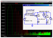
So far I see lots of local feedback playing coy by claiming to be “no (global) feedback” amplifiers –my intention is not to drag this back into the semantics morass but to point out a no feedback topology that is becoming more practical with the increased DSP horsepower available nowadays
pre-distortion correction is a widely used technique in RF amps where loop delay prevents useful amounts of negative feedback
the sim below illustrates the possibility and is “fair” in the sense that the “pre-distortion math” block absolutely does not look at Q2 output - it only operates on the input signal and an internal model of the output stage:
Attachments
Charles Hansen said:However, there is a alternative way of looking at a cascode operation that is much more intuitive. Think of a cascode transistor (for the purposes of the present discussion) not as a common base amplifier, but instead as an emitter follower.
Why an emitter follower? Its input is clearly common to its base, not its collector.
se
jcx said:the sim below illustrates the possibility and is “fair” in the sense that the “pre-distortion math” block absolutely does not look at Q2 output - it only operates on the input signal and an internal model of the output stage:
Quite so. Instead of feedback, what you have is prescience.
se
Charles,
This is getting really good, what you have to say makes a lot of sense. I had not considered the cascode as an emitter follower..........more food for thought.
Now is we can get Steve Eddy to see the light..............wishful thinking, I suppose. 😀 😀 😀
Regards,
Jam
This is getting really good, what you have to say makes a lot of sense. I had not considered the cascode as an emitter follower..........more food for thought.
Now is we can get Steve Eddy to see the light..............wishful thinking, I suppose. 😀 😀 😀
Regards,
Jam
jam said:Now is we can get Steve Eddy to see the light..............wishful thinking, I suppose. 😀 😀 😀
If seeing a common-base configuration as a common-collector configuration is seeing the light, I'll stick to the dark. 🙂
se

Charles Hansen said:1) It changes the slope of the load line drawn across the characteristic curves. The non-cascode will have a diagonal load line cutting across the curves, while the cascode's load line will be nearly vertical.
This would appear to be our primary bone of contention. If you
can construct a load line in which two distortions compensate
for each other effectively, then Bob's your uncle.
If you can't then you're better off eliminating the sources of
distortion individually.
Well I guess I'm still not quite seeing the added linearity of a cascode. First I took the characteristic curves of a 2SA1407. Then I drew one vertical load line (red) at 10 volts to represent a perfect cascode. Next I drew a diagonal load line (gold) that represents a 333 ohm load.
Attachments
(continued from previous post)
Next I blew up the images on my screen, measured with a ruler and tabulated the points where each load line crossed each characteristic curve. These points were then plotted in Excel to give the following graph. The x-axis represent base current in uA, and the y-axis represents collector current in mA. A perfect transistor would have a straight line in this graph.
I can perhaps see a very slight advantage for the cascode at higher currents, but certainly nothing to bet the farm on especially given the level of precision available.
Attachments
- Status
- Not open for further replies.
- Home
- Amplifiers
- Solid State
- Another Zero Feedback Amplifier