On cascodes
Maybe I am getting things wrong here, but here are som thoughts
on cascodes.
1) Except for the other benefits mentioned, they also (almost)
elimiate the effect of the Early voltage of the single CE or diff pair
input, which is also a kind of lineariazation (sorry if this was
already mentioned and I missed it)
2) As for the biasing of the cascodes:
2a) For JFETs, biasing to ground does not entirely keep Vds
constant, but probably constant enough. OTOH, if we reference
the cascode gate(s) to the input stage source(s) we also get
kind of local feedback loop which might perhaps be harmful.
2b) For BJTs, we have to bias the cascode bases either at a constant
voltage relative to ground or relative to the input emitter(s). First,
the same argument as for case 2a should apply, getting a local
feedback loop in the latter case. Further, the variation in casscode
base currents not being negligible as in the JFET case, they would
also to some degree perturbate the constant tail current as seen
from the input diff pair or the emitter current in the case of a CE
stage.
Pleas note, I am not advocating either solution, just trying to
give som food for though, although I am sure this is trivial and
obvious to many readers.
Jam,
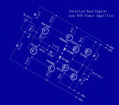
is this novelty of publishing diagonal schematics an artistic expression
(nothing I object to) or does it serve some other purpose that I
fail to see? 🙂
is this novelty of publishing diagonal schematics an artistic expression
(nothing I object to) or does it serve some other purpose that I
fail to see? 🙂
Christer,
You make some good points. I try to avoid cascodes when I can but somtimes you have to when using j-fet inputs. Now folded cascodes are another matter. I think they are great.
As for the diagonal schematic.........I was trying to throw Steve Eddy off 😀 ..........no that is the way it was when I pulled it off the web..........I could correct I think if that would please you.😉
Regards,
Jam
jam said:
As for the diagonal schematic.........I was trying to throw Steve Eddy off 😀 ..........no that is the way it was when I pulled it off the web..........I could correct I think if that would please you.😉
Although a bit harder to read, I like it from an artistic point of view.
I am an amateur painter, you know, so I like an occasional break
from the boring engineering standards. 🙂
Maybe we should start a contest. Most artistic redrawing of
schematics, not considering engineering aspects of
comprehensibility? 🙂
Christer said:Maybe we should start a contest. Most artistic redrawing of
schematics, not considering engineering aspects of
comprehensibility? 🙂
I'm game.
How 'bout this? I did it oh, I dunno, 13 or 14 years ago using a DOS version of 3D Studio on my old 33MHz 386. 🙂
Attachments
Steve,
I was actually thinking about modifying just the schematic itself,
but otherwise your photo is quite a good photo with good
composition and a nice restricted colour palette.
BTW, if people actually took this challenge seriously and want
to pursue it, I suggest starting a new thread for it.
I was actually thinking about modifying just the schematic itself,
but otherwise your photo is quite a good photo with good
composition and a nice restricted colour palette.
BTW, if people actually took this challenge seriously and want
to pursue it, I suggest starting a new thread for it.
Yep, back to circuits.
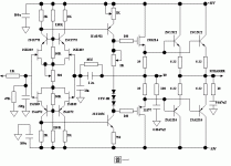
Jam, the second circuit you posted has a feedback loop that encompasses everything except the outputs themselves. The divider network is unusual in that it is a *capacitive* divider instead of a resistive divider. This is made possible because of the use of JFETs. The 30 M resistor gives 100% feedback for DC.
Jam, the second circuit you posted has a feedback loop that encompasses everything except the outputs themselves. The divider network is unusual in that it is a *capacitive* divider instead of a resistive divider. This is made possible because of the use of JFETs. The 30 M resistor gives 100% feedback for DC.
Hey Jam, do you *ever* run out of these things? 😀
Kind of an interesting circuit, and it fits in the thread if we ignore the CFPs in the output stage (like the first schematic you posted).
The pre-drivers have an interesting twist I've not seen before. That first set of emitter followers has current-source loads, which (on paper at least -- I've never actually tried it) are required to get good performance out of that configuration. But the interesting thing is that collectors don't go to the opposite rails, but instead are configured in a quasi-cascode / quasi bootstrap configuration that keeps a relatively small and constant voltage across them.
Wonder how it works... have you ever built or heard this circuit?
Charles Hansen said:The divider network is unusual in that it is a *capacitive* divider instead of a resistive divider.
Why do you suppose anyone would want to do that?
Hello Nelson,
Well, I'm not sure if you already know the answer and are just testing us, or if you are really asking....😉
In that particular circuit, I would say that it's part of his compensation scheme to keep the amp stable. There is another RC circuit to ground at that point that is clearly some sort of compensation. So I would presume that the capacitive divider also is part of the compensation.
I can't really see any other advantages or disadvantages, except that high quality capacitors are *much* more expensive than high quality resistors! Of course, I'm probably missing something...
Cheers,
Charles Hansen
I share Nelson's question. I believe there is a downside to using a charge integration chain to derive a potential difference. Firstly, errors are integrated. Secondly, the amp will not function properly if there are low frequencies present in the output. Thirdly, if the input capacitances of the JFETs are not balanced or are non-linear this will add a cumulative error to the capacitor divider. I don't immediately see any special compensation advantage.
But I'm open to enlightenment.
Ofcource capacitors store energy rather than dissipate it so there is a global warming advantage to this arrangement.
But I'm open to enlightenment.
Ofcource capacitors store energy rather than dissipate it so there is a global warming advantage to this arrangement.
Charles Hansen said:
Hello Michael,
The cascode *doesn't* make the device more linear, in general. This is probably something that was written in a magazine article one time and has been repeated so much that people think that it's true. It makes a very low impedance load for the input device. This will essentially eliminate Miller capacitance, which can be a help at very high frequencies (usually well outside the audio band). [snip]Charles Hansen
Hello Charles,
I agree with the above, but isn't there another effect? As the voltage across the transistor or FET remains constant, it also eliminates voltage dependent gain modulation. That DOES make it more linear, doesn't it? I think there was an early article by NP in Audio Amateur circa 1980, pointing this out.
Jan Didden
Good question, Jan. I think the answer is actually the opposite. If you look at the characteristic curves of either a bipolar or FET, the curves are spaced further apart as the drive signal increases. (Exponential for bipolars and square law for FETs.) The Early effect (found to one degree or another in all solid state devices) compounds this problem, making the curves grow even further apart as the drive signal increases when there is high voltage across the device.
But if you draw a resistive load line over those characteristic curves, when there is high current there will always be low voltages across the device. So the impact of the Early effect is mitigated to a large degree when using a resistive load.
Disclaimer: The above is based solely on graphical analysis. I have not verified it with simulations nor actual tests on real circuits. So it may not even be true. 🙂
On the other hand, cascoding a device will tend to eliminate the (often non-linear) Miller capacitance. This *can* create a large benefit to the stage *prior* to the actual stage in question. So it is possible that while cascoding does not increase the linearity of the stage in question, the linearity of the overall design may be increased by cascoding.
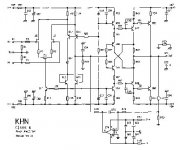
Charles,
What are the sonic effects of cascoding ( on a differential, lets say bipolar and all things being equal ie. the differential pair being able to handle the voltage without the cascode). I usually find that the cascode hurts the sound to a small degree (compression?). We are not talking about a folded cascode here.
Have you tried this on one of your zero feedback designs?
I have found that cascoding a current source usually helps.
Regards,
Jam
P.S. How about a DIY design from you.........................subtle hint😉
Attachments
Charles Hansen said:Good question, Jan. I think the answer is actually the opposite.
You could argue that the gain decrease of the device with
declining voltage compensates for the gain increase with
increasing current, but these distortions don't cancel that well.
I prefer to eliminate each distortion at the source, if I can, and
of course that would be the trick, wouldn't it? 😎
Hello Nelson,
Again, I partially agree with what you are saying and partially disagree. On the Pass Labs website, there is a white paper that shows a marked degree of distortion reduction by using a cascode on an emitter follower. I decided to go ahead and do some simulations to see if I could verify your results.
I used the same circuit and same voltages, although the output device used was the MJL3281 (since I happened to have a model for that handy). The graphs are in the form found in Douglas Self's books, where the output stage is swept between +/- 10 VDC to look at the basic linearity of the circuit. What I found was that there isn't all that much difference between the simple emitter follower and the cascoded emitter follower.
Using a generator impedance of 50 ohms, I got the following result, where red is the cascode and green is the simple emitter follower:
Attachments
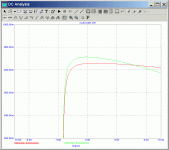
(continued from previous post)
So the cascoded circuit can seen to be flatter (more linear) in this situation. (Please note the drop off at the left side of the graph is because of the 500 mA current source specified in your article. You didn't specify a load, and I arbitrarily used 8 ohms.)
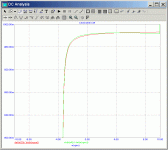
But if we change the generator impedance to 0 ohms, the situation is reversed:
So the cascoded circuit can seen to be flatter (more linear) in this situation. (Please note the drop off at the left side of the graph is because of the 500 mA current source specified in your article. You didn't specify a load, and I arbitrarily used 8 ohms.)
But if we change the generator impedance to 0 ohms, the situation is reversed:
Attachments
- Status
- Not open for further replies.
- Home
- Amplifiers
- Solid State
- Another Zero Feedback Amplifier