If I'm not mistaken, my thread where I put a unity horn clone in my car was one of the most extensive examinations of the subject ever done.
You can see it here:
unity in my car
Last night I read the synergy horn patent and it got me thinking about what I did a year and a half ago.
There were some mistakes I made, so I thought I'd examine that here in this thread. If anyone wants to pipe in with their observations, it could be an interesting examination of the subject.
For YEARS I tried to wrap my brain around what was going on in the unity horn. Read all the stuff Sheerin wrote on snippets, read what Danley wrote on audioasylum, etc... I even went so far as to build a unity out of particleboard, with four high efficiency mids bolted to the side.
One little problem - I didn't know how it worked. Results sounded muffled and weird, and I gave up for a year or so.
Later on I had a big "eureka" moment when I read some things Geddes wrote about bandpass boxes. Geddes argued that bandpass boxes and compromised horns are no different, that they're two points on a spectrum.
THAT inspired me to throw THIS together: bandpass vs horn
When someone on audioasylum said that the midranges in a Unity are no different than a bandpass box, IT FINALLY MADE SENSE. Up until that moment, I didn't "get it", that the tiny tiny amount of air in front of the midrange cones on a unity behaves very much like the front chamber of a single-reflex bandpass box.
Unfortunately, I think I got it wrong! (oops.)
I was wrong about the midranges, and so was the person on audioasylum. If the midranges were bandpass, then the volume of air in front of the cone and the length of the holes would be very important. When I made the unity, I spent a lot of time trying different hole diameters and lengths. It was frustrating because it didn't make a huge difference in the response. Yet it should have, if the "holes" are equivalent to the port in a bandpass box.
Here's how I think it actually works. As I type this it seems really obvious that this is the correct answer, but I missed it when I built my unity. The midranges AREN'T bandpass; their response is dominated by the horn that they're loaded in. So you could use the exact same front chamber volume and hole size, but if you loaded it into a unity horn that was 30" across it would have a completely different response than if you loaded it into a unity that was 10" across. I'm going to go further out on a limb and say that the depth of the holes, which I was obsessed with, isn't a big variable. The CROSS section is HUGE though.
I'm babbling here, so let me get to the point.
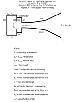
In a unity horn, the midranges are NOT behaving like a bandpass. They're behaving as if they're mounted on a conical horn, but they're NOT driving that horn at the apex. The volume of air in front of the midranges can be calculated with standard horn theory and is equivalent to an optimally sized coupling chamber. The diameter of the holes and the volume of air in front of the woofers must be sized carefully, but I do not believe that the depth of the holes should matter a whole lot, unless resizing the holes dramatically changes the volume of air.
If anyone goes and reads the synergy horn patent, they'll see where I came to this conclusion.
Attached is a pic illustrating some of these concepts from standard horn theory, thanks to Martin King.
One little problem - I didn't know how it worked. Results sounded muffled and weird, and I gave up for a year or so.
Later on I had a big "eureka" moment when I read some things Geddes wrote about bandpass boxes. Geddes argued that bandpass boxes and compromised horns are no different, that they're two points on a spectrum.
THAT inspired me to throw THIS together: bandpass vs horn
When someone on audioasylum said that the midranges in a Unity are no different than a bandpass box, IT FINALLY MADE SENSE. Up until that moment, I didn't "get it", that the tiny tiny amount of air in front of the midrange cones on a unity behaves very much like the front chamber of a single-reflex bandpass box.
Unfortunately, I think I got it wrong! (oops.)
I was wrong about the midranges, and so was the person on audioasylum. If the midranges were bandpass, then the volume of air in front of the cone and the length of the holes would be very important. When I made the unity, I spent a lot of time trying different hole diameters and lengths. It was frustrating because it didn't make a huge difference in the response. Yet it should have, if the "holes" are equivalent to the port in a bandpass box.
Here's how I think it actually works. As I type this it seems really obvious that this is the correct answer, but I missed it when I built my unity. The midranges AREN'T bandpass; their response is dominated by the horn that they're loaded in. So you could use the exact same front chamber volume and hole size, but if you loaded it into a unity horn that was 30" across it would have a completely different response than if you loaded it into a unity that was 10" across. I'm going to go further out on a limb and say that the depth of the holes, which I was obsessed with, isn't a big variable. The CROSS section is HUGE though.
I'm babbling here, so let me get to the point.
In a unity horn, the midranges are NOT behaving like a bandpass. They're behaving as if they're mounted on a conical horn, but they're NOT driving that horn at the apex. The volume of air in front of the midranges can be calculated with standard horn theory and is equivalent to an optimally sized coupling chamber. The diameter of the holes and the volume of air in front of the woofers must be sized carefully, but I do not believe that the depth of the holes should matter a whole lot, unless resizing the holes dramatically changes the volume of air.
If anyone goes and reads the synergy horn patent, they'll see where I came to this conclusion.
Attached is a pic illustrating some of these concepts from standard horn theory, thanks to Martin King.
Attachments
Thanks to the wonders of hornresp, I can take a stab at modeling midranges coupled to a conical horn.
PLEASE NOTE that I'm not aware of a way to mount the mids anywhere but the throat. Yes, I know Akabak can do this, but I don't have a Unity model for Akabak!
The way that I'm going to cope with this little problem is by taking my midrange, then determining what the parameters would be if I used four of them. For instance, VAS MMS and SD will all quadruple.
So the values I'm plugging into hornresp are for FOUR, not one.
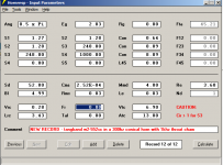
Attached are two pics, one showing the parameters for a 2inch tangband midrange which I've measured, plus a pic of the response. The paramaters I used are for a textbook horn. The sealed volume, coupling chamber, size of the holes etc...
You'll note the response is kinda crazy.
PLEASE NOTE that I'm not aware of a way to mount the mids anywhere but the throat. Yes, I know Akabak can do this, but I don't have a Unity model for Akabak!
The way that I'm going to cope with this little problem is by taking my midrange, then determining what the parameters would be if I used four of them. For instance, VAS MMS and SD will all quadruple.
So the values I'm plugging into hornresp are for FOUR, not one.
Attached are two pics, one showing the parameters for a 2inch tangband midrange which I've measured, plus a pic of the response. The paramaters I used are for a textbook horn. The sealed volume, coupling chamber, size of the holes etc...
You'll note the response is kinda crazy.
Attachments
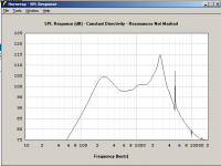
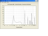
Here's the hornresp prediction of the response of the midranges in my unity horn from the thread a year and a half ago. Wow, looks TERRIBLE! 18 months ago I modeled the response using a bandpass modeling program, but it looks like the response goes to hell when you mount it in a horn.
YUCK!!!
I'll have to dig up my measurements to see how well they match up.
YUCK!!!
I'll have to dig up my measurements to see how well they match up.
Attachments
So I dug up my old data from the unity in my car.
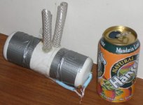
The model in the previous post is off-kilter; the actual mids I built have a smaller front chamber, shorter ports, and there are two ports per woofer, not one.
I'll post a pic of the mids next.
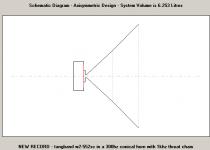
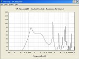
Here's an update response graph from hornresp.
You'll notice there are a lot of high frequency peaks, and the sensitivity is terrible, just 86db per watt.
This correlates to what I found when I built my unities. I had a hell of a time getting the mids to blend with the compression driver, and the level of the mids seemed to be very low.
The model in the previous post is off-kilter; the actual mids I built have a smaller front chamber, shorter ports, and there are two ports per woofer, not one.
I'll post a pic of the mids next.
Here's an update response graph from hornresp.
You'll notice there are a lot of high frequency peaks, and the sensitivity is terrible, just 86db per watt.
This correlates to what I found when I built my unities. I had a hell of a time getting the mids to blend with the compression driver, and the level of the mids seemed to be very low.
Attachments
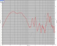
Here's the kicker.
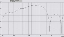
This is actual measured data of my "bandpass" midranges, coupled to a oblate spheroidal horn with a mouth of 8" x 10" and a coverage angle of eighty degrees.
You'll notice that there's a peak at 2khz and 6500hz.
In the hornresp prediction there's a peak at 1.8khz and 6.8khz.
Hmmm...
This is actual measured data of my "bandpass" midranges, coupled to a oblate spheroidal horn with a mouth of 8" x 10" and a coverage angle of eighty degrees.
You'll notice that there's a peak at 2khz and 6500hz.
In the hornresp prediction there's a peak at 1.8khz and 6.8khz.
Hmmm...
Attachments
In a unity you have two mechanisms that filter the acoustic output of the midrange driver. First you have the horn, providing a highpass function. Second you have the front chamber and the duct which connects it to the horn, which forms an acoustic lowpass. Thus, the midrange is highpass and lowpass filtered, equating in a bandpass.
I modeled this in akabak, but i am still building those things, so i have no clue about the accuracy of my script. ill post it, perhaps you find it usefull. Its a bit messy, since it was only used for my application.
System 'Unity_Segment'
Def_Driver 'WN-520N'
SD=103cm2 dD1=5cm tD1=2.5cm |Cone
fs=172.8Hz Mms=10.61g Qms=0.912
Qes=0.256 Re=6ohm Le=0.14mH ExpoLe=0.618
Def_Const | Variables are cm
{
A_Len= 2e-2; | Volumen under membrane
A_dD= 5e-2;
A_dDb= 10e-2; |
B_Len= 0.2e-2; | Front Chamber
B_dD= 10e-2; |
C_Len= 3e-2; | Ports (2 pieces)
C_dD= 0.8e-2; |
C_dDb= 3e-2;
Hi = 2.54e-2; | Horn throat diameter
Mid = 6.8e-2; | Horn width & height where the ports are
Mouth = 70.7e-2; | Horn mouth width & height
Hi_Len = 6.1e-2; | Length of the hornsegment between compression driver and midrange ports
Mid_Len = 87e-2; | Length of the hornsegment between midrange ports and the end of the horn
}
Enclosure 'E1' Node=100 Vb=0.4L Lb=0
Enclosure 'E2' Node=101 Vb=0.4L Lb=0
Enclosure 'E3' Node=102 Vb=0.4L Lb=0
Enclosure 'E4' Node=103 Vb=0.4L Lb=0
Driver 'D1' Def='WN-520N' Node=2=0=100=120
Driver 'D2' Def='WN-520N' Node=2=0=101=121
Driver 'D3' Def='WN-520N' Node=2=0=102=122
Driver 'D4' Def='WN-520N' Node=2=0=103=123
Waveguide 'Du_A1' Node=120=130 dTH={A_dD} dMo={A_dDb} Len={A_Len}
Waveguide 'Du_A2' Node=121=131 dTH={A_dD} dMo={A_dDb} Len={A_Len}
Waveguide 'Du_A3' Node=122=132 dTH={A_dD} dMo={A_dDb} Len={A_Len}
Waveguide 'Du_A4' Node=123=133 dTH={A_dD} dMo={A_dDb} Len={A_Len}
Duct 'Du_B1' Node=130=140 dD={B_dD} Len={B_Len}
Duct 'Du_B2' Node=131=141 dD={B_dD} Len={B_Len}
Duct 'Du_B3' Node=132=142 dD={B_dD} Len={B_Len}
Duct 'Du_B4' Node=133=143 dD={B_dD} Len={B_Len}
Waveguide 'Du_C1a' Node=150=140 dTH={C_dD} dMo={C_dDb} Len={C_Len}
Waveguide 'Du_C2a' Node=150=141 dTH={C_dD} dMo={C_dDb} Len={C_Len}
Waveguide 'Du_C3a' Node=150=142 dTH={C_dD} dMo={C_dDb} Len={C_Len}
Waveguide 'Du_C4a' Node=150=143 dTH={C_dD} dMo={C_dDb} Len={C_Len}
Waveguide 'Du_C1b' Node=150=140 dTH={C_dD} dMo={C_dDb} Len={C_Len}
Waveguide 'Du_C2b' Node=150=141 dTH={C_dD} dMo={C_dDb} Len={C_Len}
Waveguide 'Du_C3b' Node=150=142 dTH={C_dD} dMo={C_dDb} Len={C_Len}
Waveguide 'Du_C4b' Node=150=143 dTH={C_dD} dMo={C_dDb} Len={C_Len}
Waveguide 'CompDriver' Node=301=300 dTH=1cm dMo={hi} Len=2.54cm
Waveguide 'W1' Node=300=150 wTh={Hi} hTh={Hi} wMo={Mid} hMo={Mid} Len={Hi_Len} Conical
Waveguide 'W2' Node=150=160 wTh={Mid} hTh={Mid} wMo={Mouth} hMo={Mouth} Len={Mid_Len} Conical
Radiator 'Rad1' Def='W2' Node=160 x=0 y=0 z=0 HAngle=0 VAngle=0
Mavo, thanks for posting the model!
When I was making my unity I tried to purchase that driver that you're using. I wound up calling Loudspeakers Plus, and wasn't able to figure out a way to get it.
Months later someone emailed me, and there's a virtually identical driver available from martinsoundpro.
XT-520N
It ain't cheap - close to $100 each.
But it's one of the best ones available in the states for a Unity, alongside the 6" Ciare from Assistance Audio.
Patrick Bateman said:
I was wrong about the midranges, and so was the person on audioasylum.
IIRC that was me........ Regardless, mounted on the horn it's a 4th order (aka type 1) bandpass with a vented front and sealed rear chamber, so whoever said it was right, though feel free to try and find an alternate way to do one, for who's to say TD's is the only way? 😉
GM
i found a webshop in sweden, around 80€ per driver. but your driver is the same one. even the spec sheet is the same, only the company name is switched 😀
MaVo said:would you be so kind and post a link to the synergy patent? i cant find it with google 🙁
here is a pic of the simulation:
Here's the synergy horn patent.
GM said:
IIRC that was me........ Regardless, mounted on the horn it's a 4th order (aka type 1) bandpass with a vented front and sealed rear chamber, so whoever said it was right, though feel free to try and find an alternate way to do one, for who's to say TD's is the only way? 😉
GM
I agree there's a bandpass effect. I made one big huge fundamental catastrophic mistake with my last Unity though. I didn't "get" that the port length is damn near irrelevant.
When I was doing this the last time around, I was fixated on the volume of air in the front chamber and the length of the ports. I didn't give much thought to their diameter. Basically I varied the volume in the chamber and the port length to get the best response.
Looks like that was a big mistake - the *diameter* of the port makes more difference.
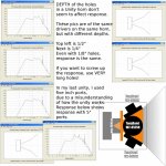
According to the synergy patent, the depth of the ports has been reduced from 3/4" in the Unity to 1/16" in the Synergy.
Using the same midrange from my posts above, I optimized the chamber volume and diameter to some extent. Then I varied the depth of the holes, and took screen caps.
In the attached pic, you can see the depth of the holes has barely any effect on the response, until they get dramatically long (like I was using.)
Attachments
The depth of the holes has an effect. But is has to be seen in combination with the hole diameter and the volume under the driver. Small diameter needs small length and the other way round. If you get too small, you loose overall sensitivity, too big only has diffraction and resonance effects on the tweeter signal. The holes together with the volume between them and the membrane form an acoustic lowpass. You have to figure out a good combination of volume, hole length and hole diameter, either by building and measuring or by simulation. Hornresp isnt good for this, since you cannot model the volume between holes and membrane and this is why it doesnt seem to have an influence in your observations. Use my script and you can see what the effect is.
Danley could reduce the size of the holes, because he made them bigger on the side of the drivers, so they look like a truncated cone, the smaller side on the horn side, the bigger side near to the membrane. you can model this in my script as well.
Danley could reduce the size of the holes, because he made them bigger on the side of the drivers, so they look like a truncated cone, the smaller side on the horn side, the bigger side near to the membrane. you can model this in my script as well.
The tapered port 132 is preferably defined by frustoconical wall 134 having a large end adjacent driver 20 and a smaller end adjacent the outer surface 136 of the horn wall.
http://www.google.com/search?as_q=&...as_dt=i&as_sitesearch=&as_rights=&safe=images
http://www.mathwords.com/f/frustum.htm
I think i saw a photo of this in diyAudio in a thread about someone's synergy or unity speaker. It wasn't so much a truncated cone as a smooth rounding down of the wall on the diaphragm side all around the duct - like the top of a funnel. Perhaps done with a grinder.
It might be worth doing a search because I seem to remember the poster saying he'd done it on Tom's advice. I also seem to remember a quite a bit of polyfilla or something like it in that area. 😉
I think the poster was pleased with overall results.
My guess is that the idea behind this is to get the compression impulse down the duct efficiently with least turbulence
USPTO gives good pictures if you use Alternatiff.
MaVo said:The depth of the holes has an effect. But is has to be seen in combination with the hole diameter and the volume under the driver. Small diameter needs small length and the other way round. If you get too small, you loose overall sensitivity, too big only has diffraction and resonance effects on the tweeter signal. The holes together with the volume between them and the membrane form an acoustic lowpass. You have to figure out a good combination of volume, hole length and hole diameter, either by building and measuring or by simulation.
Agreed.
horn physicsDanley could reduce the size of the holes, because he made them bigger on the side of the drivers, so they look like a truncated cone, the smaller side on the horn side, the bigger side near to the membrane. you can model this in my script as well.
- Status
- Not open for further replies.
- Home
- Loudspeakers
- Multi-Way
- Another Unity Horn