Russ thank you for the input. I did some more testing. It looks like having it switched to 820ohm position should yield better results. I will have to let it run for a while tomorrow and see how it goes.
Well I am on to my second simpleSE. I am looking to make it more industrial looking cosmetically. I am debating about installing two meters that will measure bias current. If I understand correctly I would wire the meter in series with r17/r27. Also wouldnt I have to account for the resistance of the meter? The meters I am looking at do not give the resistance but it does list that the ES=1maDC. So are they saying the effective resistance is 1ma? I am not too sure what they mean by ES.
Instead of getting an ammeter, I'd find a voltmeter ranged for 1 volt full scale. Add an extra 10 ohm precision resistor in series with the cathode resistor on the board. You might even be able to mount it all on the board, building a little triangle shaped thing. You can see the big white cemented cathode resistor on the left. The little black resistor to the right could be a precision 10 ohm part. It only needs to be rated for 1/2 watt, since 98% of the power will be dissipated in the cement resistor.
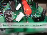
Put your voltmeter in parallel across the 10 ohm precision resistor. A reading of one volt would indicate 100 milliamps.

Put your voltmeter in parallel across the 10 ohm precision resistor. A reading of one volt would indicate 100 milliamps.
Well I am having issues sourcing a full scale 1volt meter. But I have found some 1ma meters that can be had cheaply. Here is what my research has come up with in finding the resistor value.
So if I want to measure 100ma full scale one a 1ma meter I would first need to find the resistance of the meter(mR). Then take mR/99=resistor to be in series with r17. So for example:
Meter Resistance = 89ohms
Meter Scale= 1ma
Desired Measure= 100ma
89/99=.9ohms
So I will parallel the meter with a .9ohm resistor
Here is a diagram I was looking at that depicts it nicely
Im still super new to all of this but reading has been helping out a bit
So if I want to measure 100ma full scale one a 1ma meter I would first need to find the resistance of the meter(mR). Then take mR/99=resistor to be in series with r17. So for example:
Meter Resistance = 89ohms
Meter Scale= 1ma
Desired Measure= 100ma
89/99=.9ohms
So I will parallel the meter with a .9ohm resistor
Here is a diagram I was looking at that depicts it nicely
An externally hosted image should be here but it was not working when we last tested it.
Im still super new to all of this but reading has been helping out a bit
nic6paul said:...I would first need to find the resistance of the meter(mR).
Don't ever stick a voltmeter directly across the terminals of an ammeter in an attempt to measure it's DC resistance. You'll likely fry the meter winding. There's a method where you build a network around the meter, and calculate the meter's resistance from that. Search around, and you'll probably turn it up.
I actually picked up a couple off of fair radio. BTW your box was put in the mail last week sometime. You should be getting it soon I would think.
I got the meters today. No markings as to internal resistance. Now I was wondering before I start testing the internal resistance via one of the methods I found on the net. I was wondering if adding a high value resistor(4k) in series with it and measure the resistance. Then measure the resistor and do the math. For instance the resistor measured in at 3995 ohms and when placed in series with the meter you measure 4100 ohms. Simple math and you get 105ohms. I cant imagine it would be that simple.
nic6paul said:I got the meters today. No markings as to internal resistance. Now I was wondering before I start testing the internal resistance via one of the methods I found on the net. I was wondering if adding a high value resistor(4k) in series with it and measure the resistance. Then measure the resistor and do the math. For instance the resistor measured in at 3995 ohms and when placed in series with the meter you measure 4100 ohms. Simple math and you get 105ohms. I cant imagine it would be that simple.
I'd go higher. You need to avoid putting more than 1ma through the meter. All of my meters use 9v batteries - so worst case is 9v/4000 which is 2ma
I'd using something like a 10k
nic6paul said:I got the meters today. No markings as to internal resistance. Now I was wondering before I start testing the internal resistance via one of the methods I found on the net. I was wondering if adding a high value resistor(4k) in series with it and measure the resistance. Then measure the resistor and do the math. For instance the resistor measured in at 3995 ohms and when placed in series with the meter you measure 4100 ohms. Simple math and you get 105ohms. I cant imagine it would be that simple.
Something like that ought to be safe for the meter, assuming the added series resistance is sufficiently large. But, it's going to limit your accuracy. On my DVM, I would need to set it to the 20k range in order to measure the total resistance. I'd only get two significant digits, and the portion contributed by the meter you are testing might very well fall into the noise.
Here's a better approach involving the use of adjustable pots and a 1.5v supply:
http://www.diyaudio.com/forums/showthread.php?postid=1168394#post1168394
Be sure to read Brian's comments two posts down for further improvements on the method.
Well I got the whole meter resistance value resolved. It came out to 104 ohms. So with knowing that I want to change the scale of my meter to 120ma. The reason I went with 120 is the way the scale is laid out on the front it has six parts to it so it would make it easier to read in that scale. Fullscale currently is 1ma.
Anyone want to check my math here
Meter resistance=104ohms
Full Scale=1ma
Desired Scale=120ma
104/(.12/.001)=.867ohms
It took me some time to find some values that would work but I found a couple of wirewound resistors(7ohm 3w and 1ohm 1w) that when paralleled with the meter will yield .867ohms.
1/((1/7)+(1/1)+(1/104))=.867
Does this sound right to everyone?
- Status
- Not open for further replies.
- Home
- More Vendors...
- Tubelab
- Another TubeLab SimpleSE Build