It looks like Digikey is out of the CL90 Inrush Current Limiter but I think I have found a comparable one over at mouser: Part Number 527-CL90
Also any opinions on a bleeder resister for the motor run capacitor. I want to make one order for the remaining parts.
I forgot to add that I have already upgraded to the larger Edcor OPT. I needed to do something with some of my tax return 😉
Also any opinions on a bleeder resister for the motor run capacitor. I want to make one order for the remaining parts.
I forgot to add that I have already upgraded to the larger Edcor OPT. I needed to do something with some of my tax return 😉
Bleeder Resistor:
There are two bleeder paths already present on the board. As mentioned R2 is a bleeder directly across the input capacitor C1. The series combination of R3 and R4 are wired across the main filter cap C2 (and the supplemental capacitor). This provides a bleeder for both capacitors in the event that the choke or one of the bleeder resistors fails.
An additional bleeded should not be necessary for the supplemental cap, but there is a very small possibility that the wiring from the board to the cap could become open due to a loose connection. If you want to have this possibility covered add a bleeded resistor directly to the capacitor terminals. Use a 150K 3 watt resistor of the same type as R2.
James OPT:
I have not used James transformers so I don't know how they are wound. They may invert (like the Edcors) or may not. If wired incorrectly cathode feedback will increase the gain instead of reducing it. If the amp appears louder with feedback connected than without it, this is the case. If so swap the 0 and 8 ohm connections right at the transformer. You may need to try it both ways, you want the connection that reduces the gain (lowest volume).
How prone are film/oil caps to dielectric absorbtion?
If you want the cap to have it's own bleeder for when you leave it disconnected, you can solder one directly across it. I would consider going with something bigger than the one on the PCB because it will be yet another shunt load on the power supply. Maybe 220k.
If you want the cap to have it's own bleeder for when you leave it disconnected, you can solder one directly across it. I would consider going with something bigger than the one on the PCB because it will be yet another shunt load on the power supply. Maybe 220k.
After experimentation, for the lowest volume,
I must connect the negative (black) binding post and the 8 ohms (of the 6123HS OPT)
The positive (red) binding post and the 0 ohms (of the 6123HS OPT)
My question, the negative binding post and the 8 ohms (OPT)
are connected to T2-SEC-1 or to T2-SEC-2 ? Is-it makes a difference ?
I must connect the negative (black) binding post and the 8 ohms (of the 6123HS OPT)
The positive (red) binding post and the 0 ohms (of the 6123HS OPT)
My question, the negative binding post and the 8 ohms (OPT)
are connected to T2-SEC-1 or to T2-SEC-2 ? Is-it makes a difference ?
Well I am on the home stretch of building this amplifier. I have already made upgrades to some components even before it has been built. I changed the power transformer to the edcor xpwr059 and the opts to the csxe series. I just got a message saying the OPTs have shipped now just waiting on the power trans. I have been doing some finishing work to the chassis design. I got it built just need to decide how the feet will be attached, finish the aluminum top plate and create a bottom plate. Now on to one last question before I finish:
I was thinking of creating an adjustable cathode bias switch using an on/off/on dpdt toggle switch. The off position I was thinking of having a 750 ohm resistor in place that would be selected when I want to use a pair of el34s, then when the switch is flipped up a 2.2k ohm resistor is paralleled with the 750 ohm resistor to give a value of ~560ohms to be selected when I want to use a pair of kt88, and finally when flipped down a 7.5k ohm resistor parallels with the 750ohm resistor to give a value of ~680ohms for use with the 6l6gc's. Does my logic sound reasonable to everyone?
Now I need to find another project to use my extra transformers for once I finish this one.
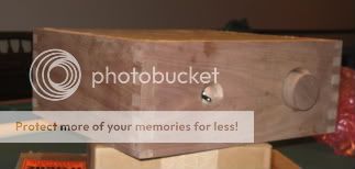
Here is a quick shot of the chassis. It is unfinished, hasnt been sanded even. Just mocked up to get some what of an idea of what it will look like. I also cut it down another good inch so it is only 4 inches tall now.
I was thinking of creating an adjustable cathode bias switch using an on/off/on dpdt toggle switch. The off position I was thinking of having a 750 ohm resistor in place that would be selected when I want to use a pair of el34s, then when the switch is flipped up a 2.2k ohm resistor is paralleled with the 750 ohm resistor to give a value of ~560ohms to be selected when I want to use a pair of kt88, and finally when flipped down a 7.5k ohm resistor parallels with the 750ohm resistor to give a value of ~680ohms for use with the 6l6gc's. Does my logic sound reasonable to everyone?
Now I need to find another project to use my extra transformers for once I finish this one.
Here is a quick shot of the chassis. It is unfinished, hasnt been sanded even. Just mocked up to get some what of an idea of what it will look like. I also cut it down another good inch so it is only 4 inches tall now.
Nice joinery! I wish I could do some box joints for mine, will have to make do with biscuits or screws just yet!
On the subject of your adjustable cathode bias switch - there is a good thread about using a switch....
http://www.diyaudio.com/forums/showthread.php?postid=1526165#post1526165
Lee
On the subject of your adjustable cathode bias switch - there is a good thread about using a switch....
http://www.diyaudio.com/forums/showthread.php?postid=1526165#post1526165
Lee
nic6paul said:
I was thinking of creating an adjustable cathode bias switch using an on/off/on dpdt toggle switch. The off position I was thinking of having a 750 ohm resistor in place that would be selected when I want to use a pair of el34s, then when the switch is flipped up a 2.2k ohm resistor is paralleled with the 750 ohm resistor to give a value of ~560ohms to be selected when I want to use a pair of kt88, and finally when flipped down a 7.5k ohm resistor parallels with the 750ohm resistor to give a value of ~680ohms for use with the 6l6gc's. Does my logic sound reasonable to everyone?
I have mentioned a couple of times to people building this that selectable cathode bias is a great idea. Here is a link to one thread where I mention it:
http://www.diyaudio.com/forums/showthread.php?postid=1526165#post1526165
The way I did it was super simple. I used some cable ties to strap together an 820R, 1.0K and 2.2K. The 820R was on the bottom and will be soldered to the board normally. Before attaching to the board, solder one leg of each of the 1.0K and 2.2K to one leg of the 820R. The other legs of the 1.0K and 2.2K are wired to a switch and back to the other leg of the 820R. So, you select between open cct on the switch to give 820R for 6L6, 597R for EL34 and 450R for KT88.
I suppose if I knew what my actual b+ voltage was it would be easier to pick the values of my resistors. I was thinking of splitting the difference for the 500v and 450v values. So if at 450v B+ a z of 5k and rk of 750 and for 500v b+ a z of 5k and rk of 910. Take the average of that to give me a resistor value of 830ohms. So for running the El34s I have I would flip the switch to give me a resistance of ~830ohms I am not sure if it is that simple. But I would be willing to bet my transformer will perform similar to the hammond 374bx which you found to give you a high b+(around 480v). My thoughts might not be right just something that I thought might work.
Thank you. I actually just made a simple jig that anyone could do with scrap wood. It broke a couple of times. I found it to be very sensitive due to how tight you had to fit everything together. If I do it again I will buy a jig from MLCS to make life simple. But I am very happy with how it turned out.Nice joinery! I wish I could do some box joints for mine, will have to make do with biscuits or screws just yet! On the subject of your adjustable cathode bias switch - there is a good thread about using a switch.... http://www.diyaudio.com/forums/show...165#post1526165 Lee
I have started with EL34, so have soldered a pair of c.770ohm resistors to the board, when I redo the chassis (first one is prototype) I'll add a switchable setup (maybe - as I'm very happy with the EL34's).....
My resistors are badged 820ohm, my local didn't have any 760ohm, but I noticed the tolerance of the 820's was pretty shoddy, so I took my multimeter along and found some at the 760 or so mark..... at least I know they are matched!
Lee
My resistors are badged 820ohm, my local didn't have any 760ohm, but I noticed the tolerance of the 820's was pretty shoddy, so I took my multimeter along and found some at the 760 or so mark..... at least I know they are matched!
Lee
I'm running 810 ohms in mine (560 ohms + another 250 ohms). My power transformer is a Hammond 374BX.
I started with 560 ohms which was fine for KT88, but too much for the smaller tubes (EL34, 6CA7, 6L6GC, 6p3s-e). The 810 ohms runs them much more gently.
I started with 560 ohms which was fine for KT88, but too much for the smaller tubes (EL34, 6CA7, 6L6GC, 6p3s-e). The 810 ohms runs them much more gently.
Too late to edit...
Here is another post mentioning much the same thing:
http://www.diyaudio.com/forums/showthread.php?postid=1652837#post1652837
Here is another post mentioning much the same thing:
http://www.diyaudio.com/forums/showthread.php?postid=1652837#post1652837
Just picked up a handful of vishay resistors. I will populate the board with an 820 ohm resistor and have on a terminal strip mounted a 9kr to give 750ohm, 3.5kr to give 660ohm, 1.8kr to give 560ohm, 4kr to give 680ohm. I think I will have my bases covered with those. I plan to only have three adjustments available so I will be leaving some out of the circuit. It sounds more complicated than it is. I based most of my decisions off george's tables. I tried to keep it with in the safe areas of each tube.
I am allowing my self some room for upgrades with 450v B+ I can use the 9k to get 750 ohm for the el34s, the3.5k to get 660ohm setting for the 6l6gc, and the 1.8k to get 560ohm setting for a pair of kt88s.
If I ever have a 500v B+ I can swap in some resistors to get 820ohms for my el34s, 4k to get 680ohms for my 6l6gcs, and 1.8k to get 560ohms for the kt88s.
I am over complicating this lol. Oh well. Back to what I know. Wood working
Well I got it up and running....BUT. I hit the switch. Tubes started to glow. Got a loud hum in the speakers then the fuse blew. Going to have to investigate. Anyone have any ideas of what I should be paying close attention to here.
Wrote too soon. Mixed up a wire.....that is what I get for being a cheap *** and using another red wire....woops. I will post some listening findings later but wow it sounds good.
Even though my mix up caused a few blown fuses it is totally operational and wow does it sound great. Even with these junk 3 way technic speakers I have this thing sounds fantastic. My wiring is not as neat as I wish but my chassis is kind of cramped. Even though a lot of wires are very close together and a bit messy...controlled mess, I have zero hum. The one thing I would suggest if I were to do this again is wait until you get all your parts before you start designing your chassis. I will get some final assembled pictures up here maybe during the week. I think I will be playing with this for a while before it gets finished lol.
After a week of flawless operation I am extremely pleased. I didn't even expect it to sound this good. With the exception of finishing off the bottom plat of my chassis I am finished. As you can see in the photo below I have it sitting on wood blocks for now. Don't worry no one but myself is around the amplifier that would come into contact with it. Now my final question is I want to double check my B+ to ensure my bias resistors are where I want them. I made an adjustable bias switch. I was wondering where should I measure on the board to get the B+ reading.
On to the photo:

On to the photo:
Looks great, paul!
Where the blue wire from one of the OPTs connect to the PCB. This is B+ after losses through the transformer...the actual plate voltage. You can then subtract the voltage you measure across the cathode resistor to get the actual voltage across the tube. Then you can easily calculate plate dissipation (for triode).
One trick when calculating the cathode current is to measure the resistor value while it is still hot. Do this by connecting the meter(s) across the cathode resistors and write down the voltages after the amp has been on for at least a few minutes (with no input). Then shut off the power and wait for the cathode voltage to drop below a volt or so. It should now be safe to switch the meter over to measure ohms. The value will change as the resistor cools, but wait at least a few more seconds for the tube to completely stop conducting. This is closer to the actual resistance while operating.
nic6paul said:I was wondering where should I measure on the board to get the B+ reading.
Where the blue wire from one of the OPTs connect to the PCB. This is B+ after losses through the transformer...the actual plate voltage. You can then subtract the voltage you measure across the cathode resistor to get the actual voltage across the tube. Then you can easily calculate plate dissipation (for triode).
One trick when calculating the cathode current is to measure the resistor value while it is still hot. Do this by connecting the meter(s) across the cathode resistors and write down the voltages after the amp has been on for at least a few minutes (with no input). Then shut off the power and wait for the cathode voltage to drop below a volt or so. It should now be safe to switch the meter over to measure ohms. The value will change as the resistor cools, but wait at least a few more seconds for the tube to completely stop conducting. This is closer to the actual resistance while operating.
Well I measured across the cathode resistors and I got 40 volts roughly across each does this sound about right with a 660ohm resistor. I also did what you said about checking the the resistance when it was hot and I can't remember exactly but I think it measured around 705ohms.
OK, so 40/700 = ~57mA. You can calculate the plate dissipation in triode by subtracting the cathode resistor voltage and the drop across the transformer from the B+ and multiplying the result with the current. If we assume a B+ of 450V and a 10V drop across the transformer:
450 - 10 - 40 = 400V across the tube
400 * 0.057 = ~23W
23W is on the hot side for a 6L6 for sure. I guess those are some hot tubes.
450 - 10 - 40 = 400V across the tube
400 * 0.057 = ~23W
23W is on the hot side for a 6L6 for sure. I guess those are some hot tubes.
- Status
- Not open for further replies.
- Home
- More Vendors...
- Tubelab
- Another TubeLab SimpleSE Build