Its not really too difficult to drive an ADC directly for test purposes but you do need to deal with the differential drive and the DC offset issues. the DC offset needs optimization since it relates to some idle tones if not optimized.
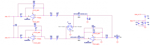
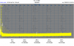
Below is the demo board input circuit. Also measured performance using the Demo board and a Shibasoku AG16 oscillator (some time ago). I think I can get better results today with better sources.
Below is the demo board input circuit. Also measured performance using the Demo board and a Shibasoku AG16 oscillator (some time ago). I think I can get better results today with better sources.
Attachments
Generator ground could be connected to the Vcom source if it's buffered. But not directly to Vcom as this would drive the Vcom output. Vcom may expressed by other acronyms on convertor data sheets. It's just a voltage reference used to bias the AC signal into the ADC input range.
Sorry about the fragmented thoughts here but my edit time ran out.
It seems that eliminating the input opamp will produce better results than any opamp added in series. Worth finding out how good just the adc is without added front end circuitry. If you can figure out how to do it.
Would another ADC be better suited to 'direct-drive' ?
THx-RNMarsh
Last edited:
The problem is protecting the the ADC input from damage. The signal has to be balance, biased with a small dc offset between the inputs. Over voltage protection would probably mess up the linearity anyway. There are single ended ADC but then there is the common mode issue.
The exercise is to determine if the ADC is more linear under direct drive. That could be done once under controlled conditions. Next is to test it with a coherent frequency and see if that improves the low level accuracy. Or just use them the way there are.
The exercise is to determine if the ADC is more linear under direct drive. That could be done once under controlled conditions. Next is to test it with a coherent frequency and see if that improves the low level accuracy. Or just use them the way there are.
The exercise is to determine if the ADC is more linear under direct drive. That could be done once under controlled conditions. Next is to test it with a coherent frequency and see if that improves the low level accuracy. Or just use them the way there are.
That is what I am asking to know about. I think the input protection is do-able problem in several ways. Myself, I would add relay auto-ranging before the ADC. The auto-ranging defaults to highest atten and works itself downward. No distortion and protected. But cost a slight amount more. On the other hand, input fets for protection like AP uses dont seem to have any affect. DC biasing ADC isnt an issue with cap coupled input.
THx-RNMarsh
The input protection in the Shibasoku 725 don't add anything either.
A diode string with leakage current cancellation.
If equal amounts of signal are place across a diode it has no effect on the input signal.
That's about how it works. If the input drives the string beyond a threshold voltage the diodes
forward bias and clamp the input. Simple and effective.
The ADCs are cmos ics. I don't know how tolerant they are with over the rail voltages at there input. The manufacture does show +/-15Vdc on the rails of the op amps so I guess the input can take at least that. Inputs are usually clamps with diodes these day so it a matter of limiting the current in a fault condition. The op amp current limiting would activate under an
over drive condition.
ADCs are a bit expensive for trial and error.
Unfortunately Japan keep the inners of their ICs secret so we don't know what's there.
The input impedance of the ADC is pretty low and not very linear. Its not a good idea to expose it directly to the I/O interface. If you look at SG's measured results the I/O interface they use or one like the Shibasoku could get the necessary linearity with a low output impedance. Not easy. However there are a number of opamps that do have better linearity that even the best ADC's.
I would sure like to know whats in the AP APx 555.
I would sure like to know whats in the AP APx 555.
AP just upgraded parts to non-obsolete types and got 6dB improvement also. But I would bet a dollar the protection is the same. All we have to do is ask them.
A few weeks ago, the AP tech told me the p/n of the protection fets but I dont remember because he sent me a pair anyway. I could read it off the part if I was in california (I'm not).
It would be nice to know what the distortion limit is of the ADC direct..... the limit for T&M with that adc device. Low gen output z isnt hard to come by. We will always wonder forever if we dont find out....... maybe asking ADC designers if we dont want to test for it ourselves. Could more easily do T&M on ultra low distortion gens etc. with direct measurement.
THx-RNMarsh
Last edited:
@ Demian, No worries, I knew it got messed up. I just felt I need to disavow the comments as they ended up looking like mine. I don't need any help sometimes as I do them myself.
I appreciate the fact that you mentioned it. Hope you are doing well and your are enjoying your new digs.
Cheers,
Sync
I appreciate the fact that you mentioned it. Hope you are doing well and your are enjoying your new digs.
Cheers,
Sync
Richard-
I have the dev board and could connect a balanced drive to the ADC. Most likely it would need to be a KH4402, for the 50 Ohm source balanced drive, which I do not have. And some tweaking to get the biasing right with coupling caps. it would be interesting.
To go further you would parallel both channels of the ADC on the input and use some simple DSP to add them. This would get a 3 dB improvement on SNR and possibly some improvement in linearity. This can continue for SNR but not for linearity. At $22+ ea the ADC's are not played with casually.
Demian, I had found same distortion on EMU1616m and shibasoku AG16A and 725C tied together and it seems due to EMU's input protection diode ,bidirectional zener input to GND.
I got schematic here "http://forum.ixbt.com/topic.cgi?id=90:1266-12"
Thanks for the poster.The thread is still running and updating schematics.
EMU have patchmix DSP to sum inputs capability so I also tested paralleling but it do not reach 3dB SN gain with two inputs. I do not know cause of it yet.
Linearity view, even order distortions can be canceled with flipping one input's polarity both on the physical input and the DSP function.
Summing outputs are more easier, but on my unit output ch 3 have better THD ,ch 1 and 2 is worse, so paralleling improves SN but messes THD at high level.
Last edited:
I just got another 1616M and have compaired them in the line in 1 on the rear. The one I just got measures as low as .00019% THD where the one I have had measures .0004%. Both are quite good. best measurement around -10 dBFS.
Native windows audio doesn't work to a useful level in Win 10. ASIO does work well.
I looked at the schematics on the Russian site and will compare against what I know of the boards. Zener diodes are not really good for this stuff. Diodes clamping to rails work much better and have less impact on the signal.nThe opamps were good but much better exist today.
Using the chassis mounted board 1212m brings too much ground related stuff to be usable at these levels of performance. I'll try it in differential mode but just connecting the chassis brings a lot of junk that's not there with the 1616M.
Today I found another copy of Bob's article of the famous THD Analyzer on the internet and noticed an addendum that was published later by Bob (unknown which issue it was).
Here a copy of the text:
Addenda: THD Analyzer.
I have found that improved calibration tolerances result if the following changes in resistor values are made in the THD Analyzer:
R121: 910k to 1M
R124: 12k to 11k
R179: 2.7k to 3.0k
(See "Parts List" on page 61 of the September issue).
The third sentence of the caption for Table 3 (page 58) should read: "R (E, F, G, H) should be 5%, 1/4 watt carbon-film types where each group of four like values should be matched within 1%".
Robert R. Cordell
Might be interseting for all of you who built it or planning to.
Hi Rob040,
Thanks for putting that up. I had completely forgotten about that update and likely don't even know if I still have a copy of it. That is so very long ago. I still use my analyzer all the time.
Cheers,
Bob
Thanks for putting that up. I had completely forgotten about that update and likely don't even know if I still have a copy of it. That is so very long ago. I still use my analyzer all the time.
Cheers,
Bob
In a second Part to this tutorial we’ll look at design ideas for controlling the binary weighted attenuator with a rotary encoder, how other tapers can be created in a similar way using the same circuit. We’ll also take a look at how this circuit can be used to tune a State Variable Oscillator.
@David (davada): Just curious... Do you still have plans to write this second part? Looking forward to it...
Hi Folks,
having just come across this thread, I thought I would bump it to see if it has progressed.
If it branched off somewhere else, could someone kindly send me the link.
Thanks
Mike
having just come across this thread, I thought I would bump it to see if it has progressed.
If it branched off somewhere else, could someone kindly send me the link.
Thanks
Mike
kinda fizzled out.
i think most folks having interest in a DIY analyzer went with computer + GOOD sound card or refurbished classic gear (like HP 339).
Bob's project needs a little reworking to make it more realizable today - for example, those ganged rotary switches would be tough to find now. so likely easier to do with relays.
depends on how much DIY you're willing and able to do ...
mlloyd1
That's right. Sound cards with software, the AudioAsylum QA401, and refurbished classic gear are probably the right way to go for most folks these days. Things have changed a lot in terms of what is available at a reasonable price.
My THD analyzer was a very challenging project even at the time, and those rotary switches were expensive and indeed would be hard to find these days.
The performance was excellent, and I still use it regularly to this day. It blows away the unmodified HP339A that I have, both in terms of noise and residual THD. My analyzer can do THD+N in a back-to-back arrangement of about 0.0003% at 1 kHz and 0.0006% at 20 kHz. But I believe in another thread here folks have gotten pretty amazing performance out of substantially modified HP339A analyzers.
I do like to be able to see the residual in real time, and have it available as a fairly wideband signal - bandwidth of 200 kHz when measuring THD-20. Most affordable solutions that use a PC and an ADC at the front end (soundcard, for example) have bandwidth of about 80 kHz at best (which often many classic analyzers have as an option for residual filtering). So a PC-based solution must employ an ADC with at least 192 kHz sampling rate (Nyquist of 96 kHz, which one can only approach; this gets you to the 4th harmonic of 20 kHz on a good day).
Times have changed!
Cheers,
Bob
- Home
- Design & Build
- Equipment & Tools
- Another realization of Bob Cordell's THD Analyzer