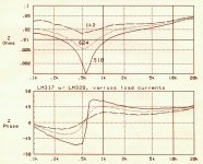
Now I wanted to see how this setup responds to load changes. Read 'em and weep below. What looks fairly nice at 13 mA becomes resonant again as the load current hits 50mA. (I labelled the bottom curve on the graph wrong, it should read 300 ohms). This is the same behavior as the resistor-only setup. Not good.
By contrast, the same test of the LM337 shows hardly any change with load in it's well-behaved curve.
So using the LM329 to lower the impedance at the adjust pin doesn't make enough of an improvement to justfy it. We still need a good, simple, positive regulator to mate with the LM337.
By contrast, the same test of the LM337 shows hardly any change with load in it's well-behaved curve.
So using the LM329 to lower the impedance at the adjust pin doesn't make enough of an improvement to justfy it. We still need a good, simple, positive regulator to mate with the LM337.
Attachments
Output impedance below 0.05 ohm across the audio band looks pretty good to me and fairly close to: http://www.diyaudio.com/forums/showthread.php?postid=1826812#post1826812
if you still think the difference is significant maybe an LT1085 is worth considering?
thanks for posting those manuals.
It seems we found the same rare articles by sandler on output phase of LM317. I really could not find anything else. I actually sent Bob Pease an email, we'll see if he replies.
sorry i can't remember the details of some of the earlier post right now can you remind me of your thoughts/data on a large electrolytic (220 or 330uF) across r2 in the adjust network. i was thinking that the higher esr of the large electrolytic may help to damp resonance. Electrolytics also tend to have smoother impedance profiles, this also helps to reduce resonance amplitude (i only mention this last point because i thought you might not be using electrolytics for those small value caps).
previously i mentioned using a large load to lower output impedance - 0.5A. this was only as an academic suggestion. According to Dietz, you can get about 95% of the gain with a 0.1 A load. Still a fair bit, but output impedance climbs steeply below 0.1 A so it is definitely worth considering.
You seeking a replacement for the LM317
what about the LM723 for a 1 USD/pcs
Almost the same price as the LM317
*150 mA output current without external pass transistor
* Output currents in excess of 10A possible by adding external transistors
what about the LM723 for a 1 USD/pcs
Almost the same price as the LM317
*150 mA output current without external pass transistor
* Output currents in excess of 10A possible by adding external transistors
Thzar: I need something TO-220 package or compatible.
okapi: Everything that my tests have shown so far says that large capacitance on the bypass pin is good for noise but bad for impedance linearity. It will be interesting if Bob Pease replies - let us know.
I think I found something at the end of my session last night that will affect my results so far. One lead from the transformer to the diode bridge broke while moving it. So I opened the transformer case to replace it and saw that I still had the 68VCT transformer in from an experiment last year. Input-output voltage differentials have been very high in my tests and that could be the cause of some of the unexpected results. I'll replace the transformer with a 32VCT one today and have another look.
Well the high input voltage (48VDC !) was causing some problems, particularly to the LM317 ripple rejection below a couple hundred Hz. But it didn't change the overall curve shapes. The input-output differential is a much more reasonable 8V now.
Look ma, new graphics. I'm porting the 4276A control program from the old HP computer to the PC, where it can generate GIF's directly as output, which makes web life easier. Still a couple loose ends to fix but it's pretty slick.
Below are a couple plots of impedance curves at various load currents. The LM337 is still by far the better of the two, and requires less load current to get it into it's stable region. And once there, it doesn't change, which is a good thing sound-wise. For the LM337, 25mA load current is fine.
The LM317 is a messier situation. It needs 50mA-100mA to get into a somewhat stable zone. But as the load goes beyond 100mA, that resonant notch at 500Hz crawls out of the woodwork. You can see it starting to form in the 100mA curve. By 150mA it is quite pronounced. So I certainly would not load it down more than 100mA, and would lean more toward the 50mA side so that dynamic current draws don't kick it into resonance. That makes things sound really thin, more so than it does already.
When the high-frequency impedance is stable while everything below it drops, I think that creates the voltage spike on the rails that okapi demonstrated in one of his experiments. And if your circuit's PSRR is worse at high freq's (aren't they all?), that gives things that "solid-state" sound that tube lovers enjoy rubbing in our noses at every chance.
Attachments
jbau the results you are posting look great.
i see you are still using the lm329 with the lm337.
i assume you still have 1500uF or so as the output cap?
have you tried the lm329 with the negative regulator?
i can send you an LT1085 if you like.
i see you are still using the lm329 with the lm337.
i assume you still have 1500uF or so as the output cap?
have you tried the lm329 with the negative regulator?
i can send you an LT1085 if you like.
unrelated device repair question
Hi Jbau, i noticed earlier you said you repaired test equipment for a living. I was hoping you could give me some advice about repairing a volt meter i have - Leader LMV-182A. I also have and LMV185A which works fine but the 182A range goes down to 0.3 mV and the 185A stops at 1mV, so i would like to get it going again.
it turns on, it gives a voltage reading, just an incorrect one.
do you happen to know any of the common problems these volt meters have?
thanks
Thanks okapi, I've been working on it all weekend. It's been a while since I did any HP Basic programming - it is bringing some old brain cells back to life 🙂okapi said:jbau the results you are posting look great.
I'm getting close to the measurement floor of the HP 4276A; .001 Ohms is the lowest it goes.
It's in my test jig but I haven't installed it in the DAC yet. I'm waiting until I get something that is as good as the LM337.i see you are still using the lm329 with the lm337.
Yes.i assume you still have 1500uF or so as the output cap?
Not yet.have you tried the lm329 with the negative regulator?
Sure, I'll have a look. But some things on the data sheet worry me - it's load regulation is worse than the 317, especially as output voltages go up. That probably means output impedance will be worse too.i can send you an LT1085 if you like.
The most common problems with all electronic equipment are electrolytic capacitors (especially high value/low voltage ones and ones in higher current circuits) and mechanical contacts. Your problem sounds like a power supply cap going bad. If you don't have a cap meter or impedance meter, check for excessive ripple on the rails. If all the caps are all good, clean/reseat mechanical contacts (switches, push-on connectors, etc.) Beyond that you probably need a manual for it....Leader LMV-182A... it turns on, it gives a voltage reading, just an incorrect one.
Hello everyone,
I am a newbie so maybe the following suggestion is irrelevant (but here it is anyway). Could using the LM117 or LM137 which are (I believe) the military version of the LM337 and LM317 help?
Regards to all,
I am a newbie so maybe the following suggestion is irrelevant (but here it is anyway). Could using the LM117 or LM137 which are (I believe) the military version of the LM337 and LM317 help?
Regards to all,
Here is what walt jung measured for the LT1085:
also, i think the 1085 has better load regulation:
LT1085 load regulation = 0.1%
LM317 load regulation = 0.3%
those numbers are from the data sheet "headline". it is hard to compare the graphs directly because of scaling issues.
My understanding is that the LM337 and the LT1033 are pretty equivalent - my transient response testing is in agreement with this. However, the LT1085 is supposed to be superior to the LM317. I have not done my transient response testing on the positive regulators yet.
I'll send you an email to arrange setting you up with a 1085.
i am not an expert programmer - just do it for data acquisition and analysis at work - it can certainly eat up the time but it can also be very satisfying work.
thanks for the info on the device trouble shooting. i retested the meter again today and it looks like it is in fact working in the ranges i could test. I am going to need to set up a different test rig to look at the 0.3 mV range setting i thought i was having trouble with in the past.
An externally hosted image should be here but it was not working when we last tested it.
also, i think the 1085 has better load regulation:
LT1085 load regulation = 0.1%
LM317 load regulation = 0.3%
those numbers are from the data sheet "headline". it is hard to compare the graphs directly because of scaling issues.
My understanding is that the LM337 and the LT1033 are pretty equivalent - my transient response testing is in agreement with this. However, the LT1085 is supposed to be superior to the LM317. I have not done my transient response testing on the positive regulators yet.
I'll send you an email to arrange setting you up with a 1085.
i am not an expert programmer - just do it for data acquisition and analysis at work - it can certainly eat up the time but it can also be very satisfying work.
thanks for the info on the device trouble shooting. i retested the meter again today and it looks like it is in fact working in the ranges i could test. I am going to need to set up a different test rig to look at the 0.3 mV range setting i thought i was having trouble with in the past.
Arick: There is no evidence the LM117 is a better performer.
okapi: You're right, the LT1085 specs better, I was looking at the 1083 before. Jung's measurement of the 317 shows the same 500Hz dip as mine.
Glad your meter is working again.
Last night's experiment compared an LM7812 to an LM7805 with a LM329 in the ground leg. The 7805/329 combo was better in every respect.
About your transient test: have you considered doing something that is closer to actual-use conditions? Limiting the rise time of the current step edges, and a lesser current step? A .5 amp step makes things look worse than they are.
jbau,
we are on the same page in regards to the transient testing. i was planning to modify my switch to mimic the load of an opamp operating in the 20-30khz range.
moving in the other direction, i also purchased a faster transistor, just to see what happens when i switch a load on as fast as possible.
other tests include an intermodulationas well as a musical waveform.
I expect to see these 3 pin regulators look near perfect with the lesser loads.
my final experiment still in the design stage is to test the transient with a big and fast load but put a shunt regulator after the the series regulator. The shunt would only need to have a 1V differential and i expect this type of configuration to completely eliminate any transient even with the toughest loads (within reason of course).
i should be back to experimenting this week so hopefully i will have some results for you.
also, your not set up to receive emails. you can change your personal settings to allow this. alternatively you can just send me one - you can see my email link if you click on my user name.
If I read you correctly then the series regulator will try to pass maximum current in an attempt to maintain output voltage and the shunt regulator will try to pass maximum current in an attempt to lower the output voltage to the set point.okapi said:my final experiment still in the design stage is to test the transient with a big and fast load but put a shunt regulator after the the series regulator. The shunt would only need to have a 1V differential
Both regulators will overheat and enter protection mode or destroy themselves.
Hi andrew,
i appreciate that you are keeping track of this thread. although i do appreciate a good explosion that is not my plan. i did not include all the details in my previous comment but there would be a series resistor after the series regulator and before the shunt.
my plan is to use the shunts locally - near the load. this assumes i can keep them from being very noisy.
that's just fine.okapi said:there would be a series resistor after the series regulator and before the shunt.
okapi
I expect to see these 3 pin regulators look near perfect with the lesser loads.
I rather doubt it. My experience tells me the transfer function will resemble the impedance curve. And these graphs all slope upward and to the right, meaning spikey high frequency modulation of the supply voltage as current is drawn.
I view the power supply impedance as a straw through which the circuitry is sucking current, and the straw is shaped like the impedance curve frequency-wise.
I'll be interested to see your current transient experiment as it unfolds.
Now here are some VERY interesting LM317 impedance sweeps, varying the input-to-output voltage differential. This should put to rest some previous speculation about this. The steps were 8V, 6.5, 5, 4, 3, and 2V. Voltage was changed by putting an autotransformer in the line and varying the AC voltage to the transformer, so no circuitry around the regulator was changed.
As you can see the i/o voltage has a very well-defined affect on the output impedance around and below the critical resonance zone. This gives us yet another ingredient to optimize the output of this regulator. Optimum zone is in the 2 to 4 volts range.
An interesting angle to this is how this will change the sound of your system when your AC line voltage changes. As it goes up, the bass will get emphasized at the expense of the mids.
Attachments
why isn't Zout rising between 1K and 20k anymore (top graph you just posted)?
what adjust at output cap values are you using?
what adjust at output cap values are you using?
Below is the overlapped impedance plots of the optimized LM317 and 337.
I haven't been able to pull myself away from listening to post anything. All I can say is - WOW. This is the most transparent, holographic sound I have ever heard coming from my system. I have absolutely no doubt of the efficacy of balanced impedance characteristics in the power supplies.
This goes way beyond LM317 land. This is one of those things that, once you hear what it does, you will never go back.
Attachments
- Status
- Not open for further replies.
- Home
- Amplifiers
- Power Supplies
- Another look at the LM317 and LM337 regulators