A Circuit Board Submission part 2
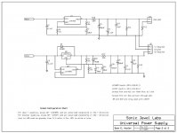
Now here's the first page of the schematic. Again, this was done in ExpressPCB's software, so it's not in an easily transportable format. I will share it with anyone who is interested. Don't worry about the official looking name on the title block - there is no commercial interest. Of course, trying to get the image down to the legal limit pretty much destroys the legibility, so...
Now here's the first page of the schematic. Again, this was done in ExpressPCB's software, so it's not in an easily transportable format. I will share it with anyone who is interested. Don't worry about the official looking name on the title block - there is no commercial interest. Of course, trying to get the image down to the legal limit pretty much destroys the legibility, so...
Attachments

🙂 Very interesting article : http://www.audiodesignline.com/howto/206800872 There are 3 pages in the first part of the article , but there are other parts: http://www.audiodesignline.com/howto/206801717 (with 2 pages) and : http://www.audiodesignline.com/showArticle.jhtml?articleID=206901915 ( with 3 pages) and : http://www.audiodesignline.com/howto/206903275 (with 3 pages) and :http://www.audiodesignline.com/showArticle.jhtml?articleID=206904733 (with 3 pages) and : http://www.audiodesignline.com/206905923;jsessionid=JL3UKRLDF0NYTQE1GHRSKH4ATMY32JVN?pgno=1 (with 4 pages)
You must be very patient in order to read all , but believe me, it's worth.
You must be very patient in order to read all , but believe me, it's worth.
Last edited:
I'm considering using this supply in a project, but I was wondering how the circuit is affected by adjusting the resistors for different voltages. Could this be made adjustable with a simple pot or would it need more serious re-tuning?
I'm considering using this supply in a project, but I was wondering how the circuit is affected by adjusting the resistors for different voltages. Could this be made adjustable with a simple pot or would it need more serious re-tuning?
I've the same question too. I want +/-12V instead of +/-15V. Would changing R2 be all that is required? (ie: keeping R1 the same as the optimized setting here)
If the current draw is 500mA, would the result be different?
Also, on the output film cap, would a plastic film cap do or does it have to be metalized polyester or metalized polypropylene film cap?
If I omit the film cap, what is going to happen?
Last edited:
I've been re-reading the thread and found the answer to the 12V question:
http://www.diyaudio.com/forums/powe...ok-lm317-lm337-regulators-23.html#post1888391
http://www.diyaudio.com/forums/powe...ok-lm317-lm337-regulators-23.html#post1888391
Hi All
Since the OP has not given a update of any testing results, his plans are just that.
The 3T adj pins Vreg band gap setting resistor is mostly fixed for general purpose usage. It' value is related to a number of things/trade-offs, one function is serving as a minimum load for the Vreg. Unless you want to dig deeper per your application, please just use the recommended (National or Linear Tech) fixed size. With adding some good filtering caps on both Vadj and Vout pins using modern small case size electro caps which are specified/designed for low esr and high temp range should give traceable performance out to 100 KHz for many years. For more info read National Semi's or the Linear data sheet, all the info you need is there.
IMO Adding additional output filters R+C and R//L+C filters are better done locally at the particular sub system or PCB component level.
Last edited:
For more info read National Semi's or the Linear data sheet, all the info you need is there.
I thought the reason for this thread was that all the info was not there. 😉
Anyway, I'm hoping to find the simplest test arrangement that will allow me to measure the performance of the regulators in my circuit.
Testing Vregs
see Linear Tech app notes like this http://cds.linear.com/docs/Application%20Note/an104f.pdf
There is also another really good one by Jim Williams on PS noise testing
see Linear Tech app notes like this http://cds.linear.com/docs/Application%20Note/an104f.pdf
There is also another really good one by Jim Williams on PS noise testing
I thought the reason for this thread was that all the info was not there. 😉
Anyway, I'm hoping to find the simplest test arrangement that will allow me to measure the performance of the regulators in my circuit.
Testing in this thread not too much 🙁 but there is quite alot of test results and charts in the data sheet, that could be extracted to fit your application circuit. The more your design deviates from the app notes test circuit the more testing YOU have to do, pretty simple huh. EDIT> OR If you use another manufactures version of that device and they haven't provided the data you need.
Last edited:
Manufacturers' data sheets do not address the point of this thread!
To leave Infinia the final contributor to this fascinating thread in which John Bau shares his painstaking original research on the sonic impact of optimizing Voltage regulator impedance and phase linearity within the audio band, is to mislead the reader that his "read the data sheet" approach is the authoritative summation of this thread.
With all due repect to Infinia, he came to this party quite late and apparently does not seem to understand the entire point of this thread nor what went on in John's investigations that required measurements that most of us are, unfortunately, not equipped to make.
The important principle to take away from this thread is that if the power supply designer pays attention to making the output impedance of his supply flat and its phase response linear within the audio band, especially when it come to matching the impedance and phase response of both positive and negative supplies, the results will have a very significant sonic improvement over a supply that is optimized just for low noise or super-low output impedance, or fast transient response.
The wise audio power supply designer would do well to learn from John, who has, IMHO, broken some new ground here. The DIY forum should be very grateful for his willingness to share with the forum members his ongoing R&D.
A careful read of this entire thread is very worthwhile.
Testing in this thread not too much 🙁 but there is quite alot of test results and charts in the data sheet, that could be extracted to fit your application circuit. The more your design deviates from the app notes test circuit the more testing YOU have to do, pretty simple huh. EDIT> OR If you use another manufactures version of that device and they haven't provided the data you need.
To leave Infinia the final contributor to this fascinating thread in which John Bau shares his painstaking original research on the sonic impact of optimizing Voltage regulator impedance and phase linearity within the audio band, is to mislead the reader that his "read the data sheet" approach is the authoritative summation of this thread.
With all due repect to Infinia, he came to this party quite late and apparently does not seem to understand the entire point of this thread nor what went on in John's investigations that required measurements that most of us are, unfortunately, not equipped to make.
The important principle to take away from this thread is that if the power supply designer pays attention to making the output impedance of his supply flat and its phase response linear within the audio band, especially when it come to matching the impedance and phase response of both positive and negative supplies, the results will have a very significant sonic improvement over a supply that is optimized just for low noise or super-low output impedance, or fast transient response.
The wise audio power supply designer would do well to learn from John, who has, IMHO, broken some new ground here. The DIY forum should be very grateful for his willingness to share with the forum members his ongoing R&D.
A careful read of this entire thread is very worthwhile.
Ground planes and such
I'm having difficulty understanding the layout for the 1085 etc.
The data sheets show a 'star' ground configuration with the main star ground point being at the load.
Does this mean that the main input ground goes onto a large plane and the load ground goes as close to the load as possible with a return ground track from there?
I have seen many LM317/337 and 1085 layouts with EVERYTHING on the large ground plane.
I've attached a crude drawing drawn by my 3 year old daughter. Please excuse her drawing abilities...she has no idea 🙂
Rob
Attachments

Without taking a side in a debate ground plane vs. star ground, I in general recommend 100 - 220 nF decoupling as closeas possible to input and output pins of linear regulators. That is, one capacitor between the ICs input pin and ground pin, and one between output pin and ground pin.
It is wise to prepare the PCB for such capacitors, and one can always leave them out of the circuit.
But, as always, read the datasheet and the application notes.
BTW it seems you have a series capacitor between the rectifier and the regulator. Probably this is intended between rectifier out and ground.
Best regds
Hi RK
That is not a series cap AT ALL but a naff symbol to show that there is a capacitor bank there in that box.
It was more about the use of a ground plane vs star as I would like to build supply as the one in this thread.
thanks rob
That is not a series cap AT ALL but a naff symbol to show that there is a capacitor bank there in that box.
It was more about the use of a ground plane vs star as I would like to build supply as the one in this thread.
thanks rob
I'm having difficulty understanding the layout for the 1085 etc.
The data sheets show a 'star' ground configuration with the main star ground point being at the load.
Does this mean that the main input ground goes onto a large plane and the load ground goes as close to the load as possible with a return ground track from there?
I have seen many LM317/337 and 1085 layouts with EVERYTHING on the large ground plane.
I've attached a crude drawing drawn by my 3 year old daughter. Please excuse her drawing abilities...she has no idea 🙂
Rob
Rob,
Proper PCB layout for Power Supplies and their regulators is critical to the performance of the regulated supply. Those who have built power supplies with just Big solid Ground Planes are just hoping that the Low impedance of the copper will sweep the problems under the rug. I routinely reduce hum and buzz and ripple from 317/1085 regulators from -50dBu or thereabouts to -85dbu or so -- mainly by fixing the layout problems on existing power supply PCBs.
There are heavy pulsing currents (Several Amps) that flow in a circle between power transfomer to rectifier to Main Filter capacitors and back to the transformer. It is critical to keep that path short and robust and in a small loop area to avoid inducing hum and buzz into other circuitry.
The Regulator's ground terminal (or in the case of the 317/1085 regulator the voltage set resistor's connection point to ground determines the reference point to which the regulator will try to regulate its output. If there are IR drops in that reference point due to heavy pulsing rectifier currents, then the output will simply follow. (Garbage in -- Garbage out).
It is important to think in terms of current paths when doing a layout for a power supply, because the currents cause voltage drops in the traces that translate to increased ripple in the regulator output.
You might want to get a consult on your layout, because if the layout is right, you will get great performance. If it is wrong, you never will.
Help please!
Hi,
I would like to build this circuit to use with a phono preamp project I am currently building. It uses +/- 15 volt supplies.
My problem however is that I am totally confused as to which LT1085 device to purchase. Would some kind person please help a novice in the UK (me!), by telling me what type I need and where is the best place to purchase from (there seems to be so many different types).
Thank you.
In the ClassA region the [current] loading [on the supply rails] is sinusoidal if the reproduced signal is sinusoidal.
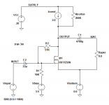
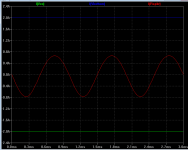
Here's a ClassA amplifier, a MOSFET implementation of a "Single Ended Triode" design. It's delivering a 1 kHz sinusoidal current into the 8 ohm load; about 2/3rds of an ampere, peak to peak. That's about 1.75 watts RMS into the 8R load. "Firstwatt" territory.
I've plotted the current drawn from the top rail (green), the current in the 8R load (red), and the current drawn from the bottom rail (blue). Try not to be annoyed by the sign of LTSPICE's "reference current direction" for the voltage sources VCC and Vbottom 😡. The plot says: the current drawn from the supply rails is constant, i.e., non-sinusoidal.
Other forum participants may wish to try the same thing on pure ClassA push-pull circuits. You'll have some fun! For ClassA push-pull, is the supply current sinusoidal? constant? neither?
Attachments
Hi RK
That is not a series cap AT ALL but a naff symbol to show that there is a capacitor bank there in that box.
It was more about the use of a ground plane vs star as I would like to build supply as the one in this thread.
thanks rob
Ahhhhh! Sorry!
/RK
Tran,
you have chosen the one ClassA single ended topology where there is constant current.
You have placed the load parallel to the driving transistor.
If you move the load to parallel to the current source (or resistor for the resistor loaded) you will have the more common version adopted by most single ended builders.
Although most builders tend to use the upside down version, i.e. driving transistor connected to +ve supply rail and resistor or CCS to -ve rail. The load is then connected from output to -ve rail.
This is the non constant current ClassA in the supply rails.
Post the results so that all can see.
- Status
- Not open for further replies.
- Home
- Amplifiers
- Power Supplies
- Another look at the LM317 and LM337 regulators